
User's Manual


Siemens PLT 111 · 1999
7/2
Coupling with other systems
Summary
Coupling with other systems
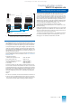
Interface modules for coupling with other systems,
summary
Summary
A differentiation is made for AS 235 couplings between
• coupling via the CS 275 bus and
• direct coupling via special interface modules.
This section only deals with direct coupling.
The summary table lists all available interface modules for cou-
pling with other systems, together with the most important fea-
tures of the modules.
All interface modules are operated in a slot for I/O modules.
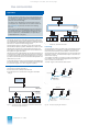
An important feature for differentiation is the type of coupling
(parallel/serial):
• With a parallel coupling, the interface module 6DS1 321-8AA
transfers all bus signals between the automation system and
the coupling partner – with the exception of the level conver-
sion signals TTL-RS 422-TTL – in real-time mode. The driver
blocks directly access the I/O modules in the connected
expansion unit with a parallel coupling.
• With a serial coupling, the interface module
s themselves han-
dle the data transfer with the coupling partner. Data transfer is
via the transfer RAM of the interface module with a serial cou-
pling.
When selecting the interface module suitable for the respective
application, the following factors may be important in addition to
the type of coupling partner:
• The distance to the coupling partner
• The topology of the system
• The earthing concept
• Measures which may be needed for lightning protection.
Since the parallel coupling is not electrically isolated and the
RS 422 system used permits a maximum difference of 7 V
between the earth potentials of the coupling partners, it is rec-
ommendable to use a serial coupling for longer distances within
buildings and for links between different buildings. As a result of
the lower number of conductors in the cable and the electrical
isolation, this facilitates any protection measures
for static and
dynamic differences in potential (earthing, lightning protection).
The transmission rate and thus the cycle time can be varied with
a serial coupling. However, the selected data transfer rate has
an influence on the maximum distance which can been covered.
The driver blocks required for the various links are contained in
the standard software of the automation system.
Coupling of other systems
The interface module 6DS1 333-8AB can be used to couple
other systems (e.g. scales, data acquisition units, process chro-
matographs) if the system has an appropriate interface, i.e.
20-mA current loop interface (TTY) and 3964 R / RK 512 proce-
dure. Other procedures and protocols require especially pro-
duced firmware. However, detailed knowledge of the module
hardware, the interface to the automation system, and the driver
blocks is required in this case.
We would be pleased to recommend software companie
s with
appropriate know-how for the generation of this firmware.
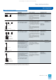
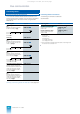
Interface module Type of coupling Interface Procedure Electrical isolation Coupling partner
6DS1 321-8AA
Parallel,
bus connection
RS 422 I/O bus interface No SIMATIC S5 expansion units
6DS1 327-8AA
Serial,
bus connection
RS 485 (ET 100) Yes SIMATIC S5 expansion units, ET 100U
6DS1 333-8AB
Serial, point-to-
point connection
TTY 3964 R / RK 512 Yes, at receiver SIMATIC S5 programmable controllers
with CP 524 and CP 544 communica-
tions processors
SIMATIC S7-400 automation systems
with CP 441-2 communications proces-
sor
SIMATIC S7-300 automation systems
with CP 341 communications proces-
sor
This catalog is out of date, see note on page 1