
User's Manual


Siemens PLT 111 · 1999
6/4
Bus communication
Design
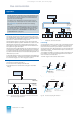
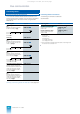
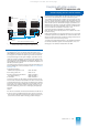
Fig. 6/6 Connection of a redundant remote bus
(AS 235 / AS 235 K/ AS 235 H)
Redundant remote bus
2 bus converters UI are required to connect an automation sys-
tem to a redundant remote bus. The bus converters are con-
nected
• in the AS 235 system via a cable 6DS9 201-8CA to the N-AS
and the connection distributor AV,
• in the AS 235 H system via a cable 6DS9 201-8FC to both N-AS
and the connection distributor AV, and
• in the AS 235 K system via a cable 6DS8 204-8MB to the N-AS.
When converting/retrofitting, cable combinations together with
the cable 6DS8 201-8.. are possible instead of the above cables
(cf. Fig. 6/6).
Local bus interface modules
Further information on the various interface modules can be
found in Catalog PLT 130 and the following manuals:
• CS 275 bus system C79000-G8076-C6
• N-V.24 coupling of computers from
other manufacturers C79000-G8076-C87
• KSN-S55 / S5-155U programmable controller C79000-G8076-C319
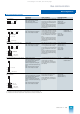
Interface module for
20-m local bus
Type
For connection of the following systems and
devices to the CS 275 plant bus
N-AS
6DS1 223-8AC
AS 235 and AS 235 K automation systems
N-AS
6DS1 223-8AA
AS 235 H automation system
N-BK
6DS1 223-8AB
Bus coupler
N-AT
6DS1 222-1AB10/20
OS 525 / WinCC/TM-OS operator systems,
AT-compatible personal computers,
SIMATIC PC and PG programming devices
N-V.24
6DS1 202-1AB
Computers from other manufacturers via V.24
or 20-mA current loop interface
N-S5
1)
6DS1 206-8AA
1) Discontinued product
SIMATIC S5-155U programmable controllers
AF
AV
UI
or
N-AS N-AS
Remote bus A
6DS9 201-8CA + 6DS8 201-8..
6DS8 201-8..
6DS9 201-8CA or
6DS8 204-8.. (without AV)
N-AS
AF
Remote bus B
UI
or
6DS9 201-8FC
with 5 plugs
Connection distributor AV
The connection distributor AV (Order No. 6DS9 207-8AA) has a
vacant plug connection to the redundant 20-m local bus for the
connection of configuring aids (e.g. personal computer with the
PROGRAF AS+ engineering tool). It must be connected to the
local bus via a cable for this purpose.
Bus converter Ul
A bus converter is required to connect individual participants or
a local bus with several participants to a remote bus. It performs
continuous signal conversion between the local bus and the
remote bus or vice versa without intermediate storage. The cou-
pling is inductive and non-reactive.
Possible locations:
• AS 235 and AS 235 H basic cabinet
• AS 235 K basic system
• Remote bus connection unit
• Bus coupler
• Remote bus connection subrack.
See Catalog PLT 130 for detailed information on the bus con-
verter.
Connector board AF "Remote bus"
The remote bus cable is connected to the bus converter via the
connector board AF "Remote bus". The board is provided with a
terminating resistor which can be activated using a jumper. The
resistor is activated in the first and last bus participants.
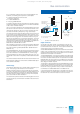
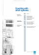
Fig. 6/7 Redundant remote bus with terminating resistors
Overvoltage protection
The participants connected to the remote bus can be exten-
sively protected against destruction by overvoltages by means
of the coarse and fine overvoltage protection units.
The coarse protection limits high-voltage signals of high power
to the arc voltage. The coarse protection is able to handle brief
peaks in the kA range. It is installed where the remote bus enters
the building. The fine protection reduces the residual voltage
which passes the coarse protection down to a value between the
internal conductor and the screen of the remote bus cable which
is harmless for the amplifier of the inductive coupler in the bus
converter. The fine protection is fitted on the connector AF.
UI UI UI UI UI UI
AF AF AF AF AF AF
aa a a
e.g. TELEPERM M
cabinet with
AS 235 H
e.g. remote bus
connection unit
(OS 525)
e.g. TELEPERM M
cabinet
Remote bus A
Remote bus B
a Terminating resistor F
(activated by jumper)
This catalog is out of date, see note on page 1