
User's Manual


Siemens PLT 111 · 1999
6/2
Bus communication
Application
Bus communication
Application
The AS 235, AS 235 H and AS 235 K automation systems are
connected together and to other automation systems and oper-
ator systems of the TELEPERM M process control system via the
CS 275 bus in medium-sized and large plants.
Central process control is carried out using the OS 525 and
WinCC/TM-OS operator systems. SIMATIC PC or other AT-com-
patible personal computers, PG programming devices and
computers from other manufacturers can be connected to the
bus system for higher-level tasks.
Sequential transfer of data between the individual participants is
in time-division multiplex mode. Participants within a local area
or a cabinet group are connected over distances of up to 20 m
by a local bus. A remote bus connects distributed systems over
distances of up to 4 km.
A redundant design of the bus line increases of the availability of
the CS 275 plant bus. The remote bus network can be extended
to a maximum length of 3 x 4 km using bus couplers.
Design
The CS 275 bus system consists of
• a local bus which is always redundant and
• a remote bus which can be either of single or redundant
design.
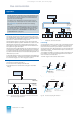
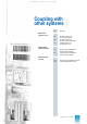
Fig. 6/1 CS 275 bus system; example of connection of local bus and
remote bus, single remote bus
AS 235, AS 235 H and AS 235 K can only be operated on the
CS 275 plant bus, but can also communicate with automa-
tion systems and operator systems on the PROFIBUS-TM
plant bus via a CS-L2 bridge.
This section only describes bus communication with the
CS 275 plant bus. A description of bus communication via
the PROFIBUS-TM plant bus can be found in Catalog
PLT 112.
When planning TELEPERM M systems with the CS 275 plant
bus, please observe the TELEPERM M design guidelines in
the manual "Information and guidelines for planning, instal-
lation and operation", C79000-G8000-C417 (German) or
C79000-G8076-C417 (English).
A
B
OS 525
WinCC/TM-OS
N-AT
UIUI
UI
Remote bus,
max. 4 km
Redundant
local bus,
max. 20 m
AS
235/K
N-AS
AS
235/K
N-AS
AS
235/K
N-AS
AS
235/K
N-AS
AS
235H
N-AS
N-AS
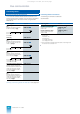
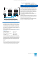
Fig. 6/2 CS 275 plant bus; example of connection of local bus and
remote bus, redundant remote bus
Local range
4 line signals are used in the local range. The data are transmit-
ted sequentially on one data line. A second line transmits the
clock, the third is used for synchronization. The fourth line is
required to switch over data transmission to channel A or B of the
redundant local bus. The wired-OR technique is used with the
local bus for coupling.
The interface modules for the local bus have a redundant local
bus interface. They are connected together with one cable in
which the local bus is redundant.
The max. length of the local bus cable is 20 m.
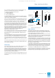
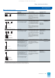
Fig. 6/3 Local bus coupling between AS 235 and AS 235 K
Fig. 6/4 Local bus coupling with AS 235 H
A
B
OS 525
WinCC/TM-OS
N-AT
UI
UI
Redundant
remote bus,
max. 4 km
Redundant
local bus,
max. 20 m
UI
UI
AS
235/K
AS
235/K
N-AS
AS
235/K
N-AS
AS
235/K
N-AS
AS
235H
N-AS
N-AS
N-AS
UI UI
N-AS N-AS N-AS
Front plug
6DS8 201-8..
6DS8 204-8../
6DS8 205-8../
6DS9 201-8CA
S max. 20 m
Max. 9 CS 275 modules
N-AS N-AS N-AS
Front
plug
6DS8 201-8..
6DS8 204-8../
6DS9 201-8CA
S max. 20 m
Max. 9 CS 275 modules
AS 235 H
This catalog is out of date, see note on page 1