
User's Manual


Siemens PLT 111 · 1999
5/5
Input and output devices
Operation unit
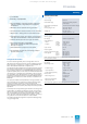
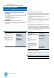
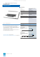
PBT 65 process operation keyboard
PBT 65 process operation keyboard
The PBT 65 process operation keyboard is used:
• To enter operating data
• For process operations (modification of operating modes,
values and statuses)
• To select area, group and loop displays
• To acknowledge messages and horn alarms.
It is possible to connect an additional configuring keyboard.
Design
The PBT 65 process operation keyboard consists of a desktop
housing with
•dust-proof and slash-proof touch pad keyboard,
• LCD unit and
• keyboard electronics.
At the rear there are connections for the configuring keyboard,
the automation system and the DC 24 V power supply.
In order to achieve the degree of protection IP 65, it is neces-
sary to protect the rear connections against dust, splashing and
gases. A keyboard attachment i
s available for this purpose as
an IP 65 kit. Without this kit, the process operation keyboard
corresponds to the degree of protection IP 20.
The two-row LCD unit of the process operation keyboard can
display 40 characters in each line. The top line is used for mes-
sages, the bottom line for the variable inscription of the 8 keys
located below it. The background can be illuminated if neces-
sary. The background illumination is automatically switched off
if no operations are made for a longer period of time.
Mode of operation
The functions of the process operation keyboard are enabled in
4 authorization stages and selected using authorization keys
identified by key switch symbols and a password.
Fig. 5/3 PBT 65 process operation keyboard
The 4 authorization stages have the following meaning:
• Stage 1: keyboard "OFF", no operation possible
• Stage 2: process operation keyboard "ON"
• Stage 3: configuring keyboard "ON"
• Stage 4: configuring keyboard and process operation key-
board "ON".
A 4-digit password which can be individually modified is
assigned to each authorization key. The last authorization stage
selected is automatically present when the PBT 65 process
operation keyboard is switched on. Transfer to a different
authorization stage is only possible if the appropriate password
is known. The authorization stage set is indicated by a yellow
LED integrated in the corresponding key.
Test mode
The PBT 65 process operation keyboard has an integrated test
mode. The test functions include initialization and deletion of
the LCD, EPROM, LED, LCD, RAM, interfaces, testing of the
authorization memory, and resetting of passwords.
A special tes
t cable which must be ordered separately is
required for this PBT test.
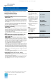
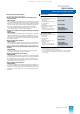
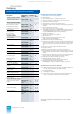
Technical data
Ordering data Order No.
Connection diagrams: see page 3/29 ff.
Summary of connecting cables with description: see page 3/34.
Automation system 20-mA current loop interface,
floating, active, 1200 bits/s
Configuring keyboard
20-mA current loop interface,
floating, passive, 1200 bits/s
Power supply
DC 24 V (18 to 33 V), 200 mA
Permissible ambient temperature
– Operation
– Transport and storage
Permissible relative humidity
0 to +40 °C
-40 to +70 °C
Max. 95 % at 25 °C
Dimensions (H x W x D) in mm
– Without IP 65 kit
– With IP 65 kit
84 x 370 x 305
95 x 370 x 373
Weight
Approx. 3.6 kg
PBT 65 process operation key-
board
6DS3 305-8BA
IP 65 kit
C79372-A3018-D1
Test cable
C79372-A3018-D2
Instruction Manual
– German
– English
C79000-B8000-C410
C79000-B8076-C410
Connecting cable
for power supply to process oper-
ation keyboard,
– With 2 plugs
– With 1 plug
6DS8 103-8
6DS8 104-8
03 m MC 5 m SC 10 m AD
Connecting cable
for connection of PBT 65 to an
automation system
6XV2 167-8C
03 m H30 25 m N25 100 m T10
05 m H50 40 m N40 120 m T12
10 m N10 50 m N50 150 m T15
16 m N16 80 m N80
This catalog is out of date, see note on page 1