
User's Manual


Siemens PLT 111 · 1999
4/3
I/O modules
Summary
Configurable I/O modules
Function modules generally have a configuration which is
defined by their firmware and which can be modified to a certain
extent by plug-in jumpers (e.g. inversion of manipulated vari-
able, internal/external definition of setpoint etc.).
The standard system software of the AS 235 automation system
also contains driver blocks for configurable function modules
from the device spectrum of the TELEPERM ME process control
system for power plants. In this case, the firmware of these mod-
ules contains an interpreter which processes a user configura-
tion generated using defined blocks. This user configuration is
produced on a personal computer in the STEP M (BG) language,
loaded into the module via a serial interface, and stored in an
EEPROM.
This principle enables the implementation of highly flexible, indi-
vidual concepts on the modules for process-oriented prepro-
cessing with direct intervention into the process whilst
bypassing the automation system. Likely applications are e.g.
balanced backup structures or particularly time-critical process
operations.
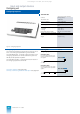
An example of a configurable signal module is the analog input
module 6DS1 731-8RR for temperature signals. The required
data on the type of transmitter, measuring range, cold junction
etc. must be defined by configuring for the input channels
(max. 32, basic module and 2 extension modules). The config-
uring data for this module are stored in a flash-PROM.
The STRUK-AS 220 EA program is required for loading/config-
uring (see page 4/6).
I/O modules
Summary of properties
• High-availability, autonomous power supply for
each I/O module; integrated power supply for
transmitters
• Modules can be replaced during operation
• Comprehensive self-test routines on the modules
• Mutual test in dialog with the associated driver
• Fault diagnosis using I & C alarms, channel-spe-
cific up to the transmitter or final control element
• Tailored driver block for each type of module
• High electromagnetic compatibility;
field inputs and outputs destruction-proof to
IEC 255-4, Class II
• Selectable backup response of modules
• Configurable modules for processing indepen-
dent of central unit
General technical data
Power supply
L
+
Rated voltage DC 24 V
Permissible range
20 to 33 V including superim-
posed ripple
Permissible superimposed
ripple
U
pp
15 % of mean value of DC voltage
Limiting range of use
35 V, max. 500 ms
45 V, max. 10 ms
Voltage dip
0 V, max. 5 ms;
recovery time min. 10 s
Process interface
• Binary signals
DC voltage Referred to potential
M
Signal definitions
– Inputs L (low)
H (high)
– Outputs L (low)
H (high)
-33 to +4.5 V
+13 to +33 V
0 to 3 V
L
+ to (
L
+ - 2.5 V)
Input currents
0.5 mA
Process signals
4mA
Output currents with DC 24 V
Max. 8.5 mA
Power signals Type 1
Type 2
Type 3
Max. 100 mA
Max. 400 mA
Max. 800 mA
Binary output signals are short-circuit-proof and overload-proof and can
be connected in parallel.
• Analog signals
DC voltage Referred to
MZ
Rated range of use -10 to +10 V
-10 to 0 V
0 to +10 V
– Overflow range
-10,5 to +10,5 V
– Input impedance
100 kΩ≤R
i
≤ 1MΩ
– Output loading capacity
3 mA
Direct current
Referred to
M
– Rated range of use 0 to 20 mA or
4 to 20 mA
– Rated input impedance
50 Ω
– Rated output load
600 Ω
All analog output signals are short-circuit-proof and overload-proof
This catalog is out of date, see note on page 1