
User's Manual


Siemens PLT 111 · 1999
4/2
I/O modules
Summary
I/O modules
Summary
The I/O modules constitute the interface of the automation
system to the process. I/O modules of the TELEPERM M process
control system are available for all common process signals,
transmitters, final control elements and automation tasks associ-
ated with process engineering.
The I/O modules are divided into:
• function modules with autonomous functions independent of
the central unit,
• signal modules (input/output modules without central-unit-
independent interventions in the process) and
• counter modules.
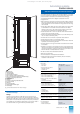
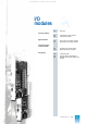
Design
The I/O modules are designed as double-height plug-in mod-
ules with a front panel width of 30.48 mm. The front panel con-
tains the module fuse, LEDs for diagnosis and error messages
and – depending on the type of module – controls, test sockets
or a plug for connection of a configuring device (configurable
modules).
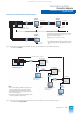
The I/O modules have 2 base plugs, the I/O bus interface and
the process interface.
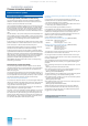
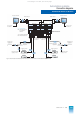
The modules are divided into 4 areas which are separated from
one another by constructive measures and circuit features. Area
1 contains the hardware for non-reactive interfacing to the
I/O bus of the automation system. This part is supplied via the
I/O bus (= 5 V bus). Area 2 contains the interference suppres-
sion and protective circuits for the process signals. These pre-
vent interfering signals from being transferred to the automation
system via the process cables as well as the destruction of mod-
ules by overvoltages. Area 3 contains the power supply circuit of
the module, area 4 the function-dependent processing circuit.
In the AS 235 system, a specific slot address is unequivocally
assigned to each I/O slot. There are two types of I/O modules as
far as addressing is concerned:
• I/O modules with jumper/slot addressing
• I/O modules only with jumper addressing
I/O modules with jumper/slot addressing should preferably be
operated with slot addressing. The I/O module is then automati-
cally assigned the slot address when inserting.
The slot address should be set on the I/O modules only with
jumper addressing using the corresponding jumpers prior to
inserting the module.
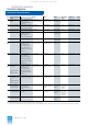
This section lists the available input and output modules of
the TELEPERM M range. A detailed description of all mod-
ules (including those which are no longer available) with
photos, functional diagrams and complete technical data
can be found in Internet at:
http://www.ad.siemens.de/teleperm
in the section "Process I/Os - TELEPERM M".
Measures to prevent interference, short-circuit and overload
Great attention has been paid to an interference-proof and over-
voltage-resistant design of the process interface.
The socket boards are divided into screening areas which are
separated from each other by grounded surfaces. These
screening areas attenuate and decouple the noise signals from
the process such that the processing circuits of the I/O modules
and the central unit are not influenced. All process inputs/out-
puts are provided with overvoltage protection circuits. Their
overvoltage resistance of 1.5 kV at 1.2
μs / 50 μs satisfies the
requirements of the IEC standard 255-4, Class II and they func-
tion correctly up to a noise voltage of 1 kV and 1 MHz.
The CE certifications apply if the TELEPERM M installation
guidelines are observed.
All analog and binary outputs are short-circuit-proof and over-
load-proof.
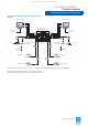
Power supply
The I/O modules only require DC 24 V as the supply voltage. All
auxiliary voltages required by the module are generated by its
own switched-mode power supply unit. Thus each I/O module
can function on its own as long as the redundant DC 24 V system
voltage is present.
As a result of the stand-alone supply and fusing of each I/O mod-
ule, the modules are largely non-reactive with respect to the
power supply. All internally generated voltages are monitored.
Voltage failures lead to an alarm in the system. Failure of the
module fuse is signalled by the separate alarm voltage
PM
on
the supply bus.
Module response upon failure of the automation system
Failure of the automation system (hardware fault, user configura-
tion in stop status, central processing unit in stop status) is
detected by the I/O modules.
The function modules have backup modes which enable opera-
tion independent of the central unit. The output modules (signal
modules) react to a reset either by retaining the last output value
or by switching to the safety setting. The desired reaction is con-
figured on the module.
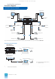
Monitoring, alarms
The functions of the modules connected to the I/O bus of the
automation system as well as their interaction with the automa-
tion system are monitored by several mechanisms. Each
I/O module monitors its own internal functions and signals e.g.
power failure, blown fuse, hardware fault in module electronics
to the automation system via the associated driver block.
The module for the I/O bus interface of the automation system
detects missing or incorrectly addressed I/O modules as well as
multiple addressing on the I/O bus. Faults in the firmware of the
module are also detected and signalled by special acknowledg-
ment procedures between the function modules and their driv-
ers. The maintenance staff are specifically guided towards the
location of a fault by means of alarms on the monitor and printer,
lighting-up of cabinet lamps and LEDs on the front panels of the
modules.
This catalog is out of date, see note on page 1