
User's Manual


Siemens PLT 111 · 1999
3/31
Automation systems
Connection diagrams
Connection of process monitors and
parallel monitors
Connection of process monitors and parallel monitors
BK2 BK1
AS 235 basic unit /
AS 235 K basic system
Process
monitor 1
116
116
117
Process
monitor *)
Process
monitor 2
Via T-pieces Via T-pieces
abc
AC 115 V or
AC 230 V
AC 115 V or
AC 230 V
AC 115 V or
AC 230 V
R
G
B
R
G
B
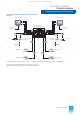
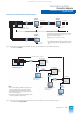
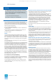
Fig. 3/16 Connection of process monitors and parallel monitors to an AS 235 basic unit or an AS 235 K basic system,
with distances up to 80 m
In the case of process monitors connected in parallel,
the total of all looped cable lengths (a + b + c + ...) is
decisive for the max. distance.
Example: a = 40 m, b = 30 m, c= 10 m
*) If the RGB video signal is looped via several monitors,
only the same picture can be displayed on all moni-
tors.
M1
M2
Mn
3 x BNC
3 x BNC
AC 115/230 V
3 x BNC
3 x BNC
AC 115/230 V
3 x BNC
3 x BNC
AC 115/230 V
Total length > 80 m, < 500 m
80 to 300 m
BK2 BK1
AS 235 basic unit /
AS 235 K basic system
Active
cable
adapter
Active
cable
adapter
(AKA n)
1st monitor in sequence,
with loop-through
BNC sockets
2nd monitor in sequence,
with loop-through
BNC sockets
Last monitor
in sequence
3 x 116
3 x 117
max. 2 m
3 x 117
80 to 300 m
3 x 117
max. 2 m
3 x 117
80 to 300 m
3 x 117
max. 2 m
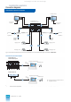
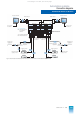
Fig. 3/17 Connection of process monitors and parallel monitors to an AS 235 basic unit or an AS 235 K basic system,
with distances from 80 up to 500 m
Note:
• It must be possible to separate the video ground
from the protective earth on the monitors (this is
already the case with the SCM 2140-I monitor).
• The 75-Ω terminators are only inserted for the last
monitor in the sequence.
• To prevent impairment of the picture quality, a max-
imum of 3 monitors should be used.
This catalog is out of date, see note on page 1