
User's Manual


Siemens PLT 111 · 1999
3/28
Automation systems
Process connection systems
Process connection systems
Process connection systems
Process signal cables, information on cable routing
The process signal cables should be screened installation
cables for industrial electronics with color-coded conductors
twisted in pairs and combined into bundles.
Highly suitable are SIMATIC cables with a conductor cross-sec-
tion of 0,5 mm² (conductor diameter 0.8 mm). In these cables,
8 pairs of twisted conductors, each identified by different colors,
are combined into a bundle. The conductors of each bundle
have a special ring identification in order to differentiate the bun-
dles.
Process cables (< 60 V) must always be routed separately from
power cables and high-voltage cables (> 60 V) (minimum spac-
ing 20 cm). Depending on the plant it may be necessary to use
a spacing of 1 m where large sources of interference are
present.
If this spacing is not possible, the cables must be routed in metal
protective tubes or in closed metal ducts with a continuous elec-
trical connection. These must be earthed every 20 m.
Suitable overvoltage arresters for lightning protection must be
provided when the cables enter and leave buildings.
Analog and binary signals must be routed in separate cables.
Signal distribution cabinets and marshalling racks must be fitted
between the process I/O peripherals and the TELEPERM M stan-
dard cabinet in the case of larger plants. These are suitable for
cross-connecting analog and binary signals and to enable
grouped connections with appropriate colors in the
TELEPERM M standard cabinet as a result of corresponding
marshalling connections.
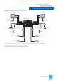
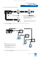
Connections for process signal cables
The process signal cables must be inserted into the cabinet
(AS 235 and AS 235 H) or housing (AS 235 K) of the automation
system from below. Their screens must be connected to the
cable clamping rails.
The process signal cables can be connected either directly, i.e.
to the base plugs X2 of the extension units (AS 235 or AS 235 H)
or to the process connection panel (AS 235 K), or also via cable
connection elements SAE (only AS 235 and AS 235 H).
Direct connection of process cables
In the case of a direct connection, the process signal cables are
directly connected to the base plugs X2 of the I/O slots (AS 235
or AS 235 H) or to the process connection panel (AS 235 K)
using the Maxi-Termi-Point system.
Base plugs X2 with wire-wrap connections are not suitable for
direct connection of process signal cables.
The slots 1 to 5 for I/O modules of the AS 235 basic unit can be
wired using the wire-wrap system or the Maxi-Termi-Point sys-
tem. Slot 6 can only be wired using the wire-wrap system. The
process signal cables leading to these slots must therefore not
be wired directly. They must be converted via cabinet connec-
tion elements SAE (Maxi-Termi-Point/wire-wrap).
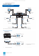
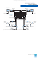
Connection of process signal cables via cabinet connection ele-
ments SAE
Using cabinet connection elements (SAE) it is possible
• to marshall within the standard cabinet between the cabinet
connection elements and the subracks,
• to convert the standard connection system (Maxi-Termi-Point
or wire-wrap) into a different system or
• to connect process signal cables to the front.
If requested by the customer, the internal system wiring between
the cabinet connection elements and the base plugs X2 of the
subracks can already be carried out in the factory. If this is
required, an SAE locating and labelling diagram as well as an
SAE wiring list must be enclosed with the order.
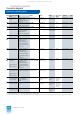
2 basic elements are available:
• Cabinet connection element SAE 32/3 (6DS9 907-8BA)
Process side: Maxi-Termi-Point pins
2.4 mm x 0.8 mm
Internal: Wire-wrap pins 1 mm x 1 mm.
• Cabinet connection element SAE 32/1 (6DS9 907-8AA)
Process side: Maxi-Termi-Point pins
2.4 mm x 0.8 mm
Internal: Maxi-Termi-Point pins
2.4 mm x 0.8 mm
The cabinet connection elements are mounted by latching into
the SAE bars on the left side of the cabinet.
Any length of cabinet connection element blocks can be pro-
duced. The bottom basic element in each case is secured using
2 Fillister head screws.
A pair of labelling cards is required for each group of 4 basic ele-
ments to label the front and rear pins. 2 types of labelling are
possible:
• For numbering of the 32 pins of a basic element from 1 to 32 or
32 to 1
(labelling cards 6XP1 846 and 6XP1 847)
• For identifying groups of 8 pins of a basic element by A to H,
e.g. for cables with color codes for 8 conductors
(labelling cards 6DS9 906-8DA).
The basic elements are numbered with the corresponding label-
ling strips according to the selected labelling cards:
• For labelling cards 1-32/32-1 for continuous or block-by-block
numbering of the basic elements
(labelling strips 6XP1 856)
• For labelling cards A-H/H-A for continuous or block-by-block
numbering of the groups of 8
(labelling strips C79165-A3012-C99)
Additional elements are available for the two basic SAE ele-
ments and enable either screw terminal connections or plug
connections at the process end. The additional elements are
plugged onto the basic elements.
Ordering of cabinet connection elements:
see pages 3/23 and 3/26
This catalog is out of date, see note on page 1