
User's Manual


Siemens PLT 111 · 1999
3/27
Automation systems
Standard cabinets
Standard cabinets IP 54 with heat exchanger
Standard cabinets with degree of protection IP 54,
with heat exchanger
Design
Cabinet with two 450-mm wide doors at the front and one
300-mm wide door at the rear. The heat exchanger is fitted on
the 600-mm wide door. Front and rear of cabinet each with a top
bezel panel with cabinet alarm lamp and lamp test pushbutton.
The cables are connected to cable bars in the rows of holes in
the cabinet frame using commercially available parts.
1
2,3
4
5
6
7
8
15
14
14
14
12
11
6
11
13
9
10
16
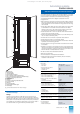
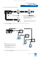
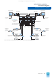
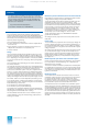
Fig. 3/12 Standard cabinet with heat exchanger
1 Cabinet housing
2 Cabinet alarm lamp
3 Lamp test pushbutton
4 Socket for telephone connection
5 Slots for video relay (AS 235 H basic cabinet only)
6 Slots for connector boards AF "Remote bus" (basic cabinet only)
7 Screen bar for connecting bus cable screens
8 Screen board
9 Three-part cable duct
10 Cable duct
11 Screen bar for connecting process cable screens
12 Bar for 24 V terminals
13 Main frame
14 Bar for fixing the cables
15 Cabinet connection element support
16 Heat exchanger
The cable bars are included in the standard delivery of the cab-
inet. The locations for installation of the video relays and the con-
nector boards for remote bus are identified accordingly.
The standard cabinet with degree of protection IP 54 is
equipped with:
• Main frame with conductive, corrosion-proof surface; fitted off-
set to one side and electrically connected to the cabinet frame.
Side members of the main frame with fixing holes for mounting
the subracks
• Three-part metal cable duct with cover plate on the right-hand
side member on the cable connection side for the ribbon
cables of the I/O bus, for power supply cables, internal bus
connections and cables to the operation devices
• Cable duct 80 mm x 75 mm on the left-hand side member for
internal wiring of process signals
• Cabinet connection element support for up to 90 32-way cabi-
net connection elements (SAE)
• Screen bars for connection of process cable screens
• Cable clamping rails for the process cables
• Screen board on the right-hand side of the cabinet for external
operation and monitoring devices
• Screen board on the right-hand side of the cabinet for remote
bus cables
• Socket for connection of a telephone to the internal telephone
network. The socket is not wired-up and is accessible from the
front of the cabinet. It consists of a two-pin plug connector 4/13
DIN 47 284 with insulated sleeve and cover
• 4 door contacts with associated cable set
• Bar for 24-V terminals
• 2 thermostats for overtemperature detection.
• Heat exchanger with forced ventilation (AC 50 Hz 230 V)
installed in the rear door
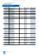
Technical data
Door width
– Front door
– Rear door
450 mm each
1 x 300 mm, 1 x 600 mm
Angle of opening of doors
– Separate cabinet
– Cabinet row
180°
135°
Degree of protection to DIN 40050
IP 54
Permissible cabinet inlet temperature
25 °C 30°C 35°C 40°C
Permissible thermal loading P
s max
– With 1 fan subassembly
– With 2 fan subassemblies
450 W 420 W 380 W 350 W
700 W
1000 W
Permis. humidity (no condensation)
– Operation
– Transport and storage
≤ 65%
≤ 75%
Heat exchanger
– Fans, rated voltage
U
n
– Power consumption per fan
– Dimensions (
H
x
W
x
D
) in mm
AC 50 Hz 230 V
Approx. 85 W
1820 x 460 x 111
Cabinet colors
– Cladding
– Cabinet frame
– Labelling strips
Acrylic resin fine-texture single-
coat lacquer
Light beige (Siemens color 103)
Gray-brown (Siemens color 105)
Ochre (Siemens color 100)
Required floor loading capacity
including weight of cables and traffic
1000 kg/m²
Dimensions (
H
x
W
x
D
) in mm 2200 x 900 x 600
Weight of empty cabinet
Approx. 180 kg
Option
Fan subassembly
– Supply voltage
– Power consumption
DC 24 V
Approx. 36 W
This catalog is out of date, see note on page 1