
User's Manual

Siemens PLT 111 · 1999
3/26
Automation systems
Standard cabinets IP 20 without heat exchanger
Standard cabinets
Standard cabinet with degree of protection IP 20,
without heat exchanger
Design
Cabinet with two-leaf doors at front and rear; lift-off doors. Each
door with 3 rows of ventilation slots.
Front and rear of cabinet each with a top bezel panel with cabi-
net alarm lamp and lamp test pushbutton.
The cables are connected to cable bars in the rows of holes in
the cabinet frame using commercially available parts.
1
2,3
4
5
6
7
8
15
14
14
14
12
11
6
11
13
9
10
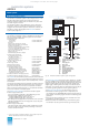
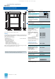
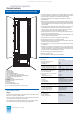
Fig. 3/11 Standard cabinet without heat exchanger
1 Cabinet housing
2 Cabinet alarm lamp
3 Lamp test pushbutton
4 Socket for telephone connection
5 Slots for video relay (AS 235 H basic cabinet only)
6 Slots for connector boards AF "Remote bus" (basic cabinet only)
7 Screen bar for connecting bus cable screens
8 Screen board
9 Three-part cable duct
10 Cable duct
11 Screen bar for connecting process cable screens
12 Bar for 24 V terminals
13 Main frame
14 Bar for fixing the cables
15 Cabinet connection element support
The cable bars are included in the standard delivery of the cab-
inet. The locations for installation of the video relays and the con-
nector boards for remote bus are identified accordingly.
The standard cabinets with degree of protection IP 20 are
equipped with:
• Main frame with conductive, corrosion-proof surface; fitted off-
set to one side and electrically connected to the cabinet frame.
Side members of the main frame with fixing holes for mounting
the subracks
• Three-part metal cable duct with cover plate on the right-hand
side member on the cable connection side for the ribbon
cables of the I/O bus, for power supply cables, internal bus
connections and cables to the operation devices
• Cable duct 80 mm x 75 mm on the left-hand side member for
internal wiring of process signals
• Cabinet connection element support for up to 90 32-way cabi-
net connection elements (SAE)
• Screen bars for connection of process cable screens
• Cable clamping rails for the process cables
• Screen board on the right-hand side of the cabinet for external
operation and monitoring devices
• Screen board on the right-hand side of the cabinet for remote
bus cables
• Socket for connection of a telephone to the internal telephone
network. The socket is not wired-up and is accessible from the
front of the cabinet. It consists of a two-pin plug connector 4/13
DIN 47 284 with insulated sleeve and cover
• 4 door contacts with associated cable set
• Bar for 24-V terminals
• 2 thermostats for overtemperature detection.
Technical data
Door width 450 mm each
Angle of opening of doors
– Separate cabinet
– Cabinet row
180°
135°
Degree of protection to DIN 40050
– Cabinet 6DS9 300-8AA (400 mm)
– Cabinet 6DS9 302-8AA (600 mm)
IP 20
IP 20
Permissible cabinet inlet temperature
25 °C 30°C 35°C 40°C
Permissible thermal load P
s max
– with fan subassembly
450 W 420 W 380 W 350 W
≤ 700 W
Permis. humidity (no condensation)
– Operation
– Transport and storage
≤ 65%
≤ 75%
Cabinet colors
– Cladding
– Cabinet frame
– Labelling strips
Acrylic resin fine-texture single-
coat lacquer
Light beige (Siemens color 103)
Gray-brown (Siemens color 105)
Ochre (Siemens color 100)
Required floor loading capacity
including weight of cables and traffic
1000 kg/m²
Dimensions (
H
x
W
x
D
) in mm
– Cabinet 6DS9 300-8AA
– Cabinet 6DS9 302-8AA
2200 x 900 x 400
2200 x 900 x 600
Weight of empty cabinet
Approx. 130 kg
Option
Fan subassembly
– Supply voltage
– Power consumption
DC 24 V
Approx. 36 W
This catalog is out of date, see note on page 1