
User's Manual

Siemens PLT 111 · 1999
3/23
Automation systems
Standard cabinets
Standard cabinets and accessories
Standard cabinets and accessories
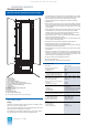
The AS 235 and AS 235 H automation systems can be delivered
in 400 mm or 600 deep standard cabinets with or without a heat
exchanger. The following standard ordering configurations are
available:
• Standard cabinet without heat exchanger, degree of protection
IP 20, cabinet depth 400 mm
• Standard cabinet without heat exchanger, degree of protection
IP 20, cabinet depth 600 mm
1)
• Standard cabinet with heat exchanger, degree of protection
IP 54, cabinet depth 600 mm
Options, to be ordered in addition:
• Upgrading set for standard cabinets, degree of protection
IP 10 to degree of protection IP 20
2)
• Fan subassembly
In the cabinets with degree of protection IP 20, heat dissipation
is by means of through-ventilation. The outside air circulates
through the cabinet and dissipates the produced heat. The dis-
advantage of this type of heat dissipation is that dirt may be
deposited if dust is present in the ambient air. This disadvantage
does not occur in cabinets with heat exchangers. The max. per-
missible thermal load is 700 W at an ambient temperature of
40 °C.
In the cabinets with heat exchanger (degree of protection IP 54),
the air within the cabinet and outside remain separated. These
cabinets must be used if the ambient conditions deviate from the
permissible values as a result of rough operating conditions.
Examples include the chemical industry, iron and steel industry,
mining, and plants exposed to salty atmospheres. The max.
thermal load is 1000 W at an ambient temperature of 40 °C.
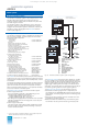
The standard cabinet can be used either without forced ventila-
tion or provided with one or two fan subassemblies depending
on the permissible thermal load of the cabinet, the desired
design and, especially, the I/O modules used.
The fan subassembly 6DS9 943-8AA is used for forced ventila-
tion. This subassembly contains three fans whose speeds are
monitored, as well as an electronic fuse.
In cabinets with heat exchangers, the fan monitoring functions of
the fan subassemblies and of the heat exchanger are connected
in series. The failure signal LK is connected to the basic unit.
Each standard cabinet has 2 thermostats to measure overtem-
peratures. See the following pages for configuring guidelines
concerning the permissible thermal load.
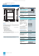
The basic cabinets are always delivered without side panels and
partitions since they can be installed individually, as double cab-
inets, or in a cabinet row depending on the location and the size
of the system. Extension cabinets are supplied with one parti-
tion. The side panels and partitions must be additionally ordered
as required.
Basic and extension cabinets can also be supplied as a double
cabinet screwed together with a low-impedance connection.
A cabinet row lamp can be fitted into the top bezel panel of the
first cabinet when installing cabinets in rows.
The rooms in which the cabinets are installed should be suffi-
ciently large (ceiling height approx. 3 m). They should also be
dry and dust-free. Air-conditioning must be provided if neces-
sary.
1) Recommended if cabinets without heat exchangers are to be installed
combined with cabinets with heat exchangers.
2) For former cabinets with degree of protection IP 10.
Ordering data Order No.
System cabinet accessories
Side panels and partitions /
mounting of double cabinets
Side panel for standard cabinets,
with mounting parts, assembled
– 400 mm wide
– 600 mm wide
6DS9 906-8FA
6DS9 906-8KA
Partition with mounting parts and
set of fittings for joining cabinets
• For 400-mm deep cabinets
– Without cut-outs
– With fire bulkhead
– With cut-outs
6DS9 906-8GA
6DS9 906-8HA
6DS9 906-8JB
• For 400-mm deep cabinets
– Without cut-outs
– With cut-outs
6DS9 906-8LA
6DS9 906-8MA
Set of fittings for joining cabi-
nets
without partition
6DS9 906-8EA
Conversion of a basic cabinet
and an extension cabinet to a
double cabinet
(delivered as double cabinet)
6DS5 707-8AA
Cabinet accessories
Cabinet row lamp
with mounting parts and connec-
tion cables, installed
6DS9 905-8DA
Cabinet connection elements
(SAE)
Cabinet connection element
with mounting screws and nuts,
assembled (max. 90 off/cabinet)
• SAE 32/3
Process side: Maxi-Termi-Point
2.4 mm x 0.8 mm
Internal: wire-wrap 1 mm x 1 mm
6DS9 907-8BA
• SAE 32/1
Process side and internal: Maxi-
Termi-Point 2.4 mm x 0.8 mm
6DS9 907-8AA
Labelling material in addition:
For connection of cables
color-coded in groups of 8
(TELEPERM M):
Labelling cards A-H/H-A for 4
cabinet connection elements,
1 pair
6DS9 906-8DA
Labelling strips for cards A-H/
H-A for 1 cabinet, 1 sheet
(2 sheets required per cabinet)
C79165-A3012-C99
For numbered designation:
Labelling card 1-32 for 4 cabinet
connection elements SAE 32
6XP1 846
Labelling cards 32-1 for 4 cabi-
net connection elements SAE 32
6XP1 847
Labelling strips for cards
1-32/32-1
for one cabinet, 1 sheet
6XP1 856
Cabinet connection element
SAE 32/3 with screw attachment
SAE 32 S
(max. 40 off/ cabinet)
Process side: screw attachment:
SAE 32 S
Internal: wire-wrap 1 mm x 1 mm
Order:
Cabinet connection element
SAE 32/3 with mounting screws
and nuts, assembled
6DS9 907-8BA
Screw attachment SAE 32 S
6XP1 828
This catalog is out of date, see note on page 1