
User's Manual

Siemens PLT 111 · 1999
3/20
Automation systems
Ordering data for AS 235 K
AS 235 K
Max. 2 interface modules N-V.24 inserted in one of the I/O slots
in the AS 235 K basic system can be integrated via a front con-
nection to the interface module N-AS of the system by means of
cable 6DS8 201-8.. . Please contact Siemens in the case of other
participants and additions.
The cable 6DS8 201-8.. is only provided with a plug at one end.
It is connected 1:1 at the free end to the plug of the N-AS. If a
cable is not yet connected there, a front plug 6DS9 200-8AA is
required in addition. The cable 6DS8 205-8.. with 2 plugs can be
used as an alternative to the combination of cable 6DS8 201-8..
and front plug.
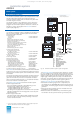
The AS 235 K is connected to a single, non-redundant remote
bus via the interface connection unit. The AS 235 K can also be
operated on a redundant remote bus. In this case, a connection
unit for redundant remote bus with 2 bus converters UI and
2 remote bus connector boards AF “Remote bus” is required.
The connection unit for single for redundant remote bus can be
selected in the standard ordering configuration under “Bus com-
ponents”. The connection unit comprises:
• Interface module for 20-m local bus N-AS 6DS1 223-8AC
• Bus converter UI 6DS4 400-8AB
(2 x with redundant remote bus)
• Connector board AF “Remote bus” 6DS9 203-8DA
(2 x with redundant remote bus)
• For single remote bus:
Connecting cable with 2 plugs for connection 6DS8 205-8MB
of N-AS to bus converter UI
• For redundant remote bus:
Connecting cable with 3 plugs for connection 6DS8 204-8MB
of N-AS to bus converters UI1 and UI2
In order to implement a remote bus, the appropriate remote bus
cable is required in addition to a connection unit for single or
redundant remote bus. This cable is connected to the connector
board AF “Remote bus” and links the individual bus participants
together at distances up to 4 km (see also Section 6).
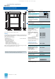
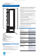
Housing
The AS 235 K is installed as standard in a sheet-steel housing
with degree of protection IP 21:
• Sheet-steel housing, degree of
protection IP 21 C79451-A3260-A50
Dimensions (HxWxD)
820 mm x 600 mm x 360 mm,
without heat exchanger, with
– separate ventilation roof,
– top panel with ventilation slits,
– front door, 600 mm wide, with lock,
– base with screwed-in cable panel,
175 mm deep, front half with ventilation slits
A diagram of the housing with dimensions can be found on
page 3/22, Fig. 3/10. When using the supplied parts set for wall
mounting, the dimensions are increased as shown in this Fig.
System documentation
German or English system documentation can be ordered with
the AS 235 K basic system. The documentation comprises:
• Manuals
– “AS 235 K automation system” C79000-G8000-C305
– “Function modules”, volumes 1 and 2 C79000-G8000-C30
– “Signal modules” C79000-G8000-C31
– “Coupling and calculation modules” C79000-G8000-C32
– “CS 275 bus system” C79000-G8000-C6
• Description “AS 235, AS 235 H and AS 235 K C79000-G8000-C416
automation systems, version G”,
volumes 1 to 3
• Manual “Notes and guidelines for C79000-G8000-C417
planning, installation and operation”
In the English system documentation, the center block of the
individual Order Nos. is replaced by “.....-G8076-...”.
• AS 235 / AS 235 H / AS 235 K table pamphlet, C79000-N8000-C1
German, order separately if required
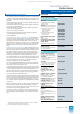
Ordering data
AS 235 K options Order No.
AS 235 K automation
system
6DS2 117- -
Basic system
• Without basic system 0
• Basic system AC 230 V, with op-
eration channel 1 and I/O bus 1
7
• Basic system DC 24 V, with op-
eration channel 1 and I/O bus 1
8
Standard I/O devices
• Without standard I/O devices X
• Configuring unit
with configuring keyboard and
mini floppy disk unit
E
• Operation unit 1 for operation
channel 1
with process monitor and pro-
cess operation keyboard
– Without configuring unit
– With configuring unit
M
P
• Operation channel 2 and opera-
tion unit 2 with interface module
for operation channel 2, process
monitor and process operation
keyboard
N
• Operation channel 2 and opera-
tion units 1 and 2 with interface
module for operation channel 2,
2 process monitors and 2 pro-
cess operation keyboards
– Without configuring unit
– With configuring unit
Q
R
Bus components
• Without bus components X 0
• Connection unit
– For non-redundant remote bus
– For redundant remote bus
X
X
1
2
Housing
• Without housing 0
• Sheet-steel housing, degree of
prot. IP 21, without heat
exchanger
1
Option:
system documentation
• Without system documentation 0 X
• German documentation 0 D
• English documentation 0 E
O
r
d
er
N
o.
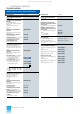
Basic system
Backup battery for memory
module
W79084-U1001-B2
Interface module for I/O bus 2
1)
1) Additionally required if I/O slot 6 is used.
6DS1 312-8BB
Bus connection of further
participants via 20-m local bus
Interface module for 20-m local
bus N-V.24
6DS1 202-8AB
Connecting cable for local bus,
0.3 m
6DS8 201-8MB
Remote bus cable
See page 6/6
Also refer to the ordering instructions in the appendix (page 8/2) with
information on ordering complete systems and options.
This catalog is out of date, see note on page 1