
User's Manual

Siemens PLT 111 · 1999
3/19
Automation systems
AS 235 K
Basic system
The central processor divides the RAM and differentiates
access operations to
• the 1-Mbyte system RAM with battery backup for all fixed
system data and programs,
• the 4000-Kbyte RAM with battery backup for all user programs
and data and for variable system data, and
• the transfer memories of the interface modules for I/O bus,
operation channel, mini floppy disk unit and local bus.
The memory module with
Error Detection and Correction
EDC
can correct a 1-bit error when reading, and eliminate it in the
memory cell together with the system software.
The interface module for I/O bus establishes the connection
between the 8-bit central unit bus and the I/O bus. One or two of
these modules can be plugged into the basic system of the
AS 235 K:
• The interface module for I/O bus 1 (A) supplies the I/O modules
plugged into slots 1 to 5 of the basic system and/or the inter-
face modules for the ES 100 K extension system. It is always
required.
• The interface module for I/O bus 2 (B) is only required if slot 6
in the basic system is to be used. It must be ordered as an
option.
Standard I/O devices
The standard I/O devices such as process monitor, process
operation keyboard, configuring keyboard, mini floppy disk unit
and logging/message printers are described in Section 5.
The interface module for operation channel generates the RGB
signals for the process monitors, including the CVS signal. It also
has three 20-mA current loop interfaces to which the process
operation keyboard PBT or the configuring keyboard and 2 print-
ers (logging and message printers) can be directly connected.
See page 3/29 for possible connections of standard I/O devices
and a summary of connecting cables.
The interface module for operation channel 1 belongs to the
scope of delivery of the basic system and is always required.
A second interface module is only required if 2 operating con-
SV1
SV2
M
L
PA
Slots
for
I/O modules
B
T
UI1 UI2
AF1
AF2
E
123456
BK2
EAB2
BK1
EAB1
AMD
BAB/DG
N-AS
CPU
RAM
SSO
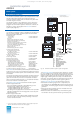
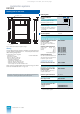
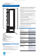
Fig. 3/8 AS 235 K automation system, design
AMD Interface module for mini floppy disk
unit
AF Connector board “Remote bus”
BAB Bus terminator module
BK Interface module for operation chan-
nel
BT Flashing pulse generator
CPU Central processor module
DG Diagnostics interface
E Power supply unit for AC 230 V or
2xDC24V
EAB Interface module for I/O bus
ML Alarm logic module
N-AS Interface module for 20-m local bus
PA Process connection panel
RAM Memory module
SSO Special interface, not used
SV1 Power supply module AC 230 V /
DC 24 V or power supply module
DC 24 V / DC 24 V
SV2 Power supply module DC 24 V /
DC 5 V
UI Bus converter
soles are to be used via which operation and monitoring or con-
figuring are to be carried out independently.
The combinations which can be ordered for the standard
I/O devices comprise:
• Configuring unit, comprising:
– Configuring keyboard 6DS3 303-8AA
– Connecting cable for configuring
keyboard, 1 m
1)
6DS8 102-8AC
– Mini floppy disk unit with cables for 6DS3 900-8AE
– signal transmission and power supply,
– 3 m each
• Operation unit, comprising:
– PBT 65 process operation keyboard 6DS3 305-8BA
– with cable for signal transmission, 5 m 6XV2 167-8CH50
– with cable for power supply, 5 m 6DS8 103-8SC
– SCM 2140-I process monitor 6GF6100-1BV
– with 3 video cables, 5 m 6DS8 116-8SC
• In addition for operation channel 2:
– Interface module for operation channel 2
2)
6DS1 330-8CA
I/O modules
The I/O modules are the process interface of the AS 235 K. They
comprise signal modules and function modules, including cal-
culation modules. See Section 4 for the properties, functions and
Ordering data of the I/O modules.
The AS 235 K has slots for 6 I/O modules. Slots 1 to 5 are con-
nected to the central processing unit via I/O bus 1 (A). Slot 6 is
connected to I/O bus 2 (B). As a result, the interface module for
I/O bus 2 must be inserted if slot 6 is to be used.
The number of slots for I/O modules can be increased up to a
maximum of 108 by connecting up to eight ES 100 K extension
systems.
The I/O modules can be supplied coded, inserted and with
labelled slots. Arrangement, designation and connection dia-
grams (including address data) are required from the orderer.
• Coding, inserting and labelling 6DS5 705-8AA
for 1 I/O module
Interface module for ES 100 K
The interface module for the ES 100 K links the I/O bus of the
AS 235 K basic system to the I/O bus of the ES 100 K via a cable.
Interface modules are required in both the AS 235 K basic sys-
tem and the ES 100 K extension system.
The interface module for the ES 100 K can be inserted into any
slot for I/O modules in both the AS 235 K and the ES 100 K.
A maximum of four interface modules for a total of four ES 100 K
extension systems can be plugged into slots 1 to 5 in the
AS 235 K.
The I/O bus 2 (B) only supplies slot 6. Therefore a further four
ES 100 K extension systems can be connected serially to the
interface module inserted there. The use of slot 6 requires that
the interface module for I/O bus 2 (optional accessory) is
inserted.
Bus components
The TELEPERM M systems can communicate with one another
via the CS 275 plant bus up to distances of 20 m (local bus) or
4 km (remote bus). The local bus is redundant as standard. The
remote bus can be redundant as an option.
Up to 9 participants can be interconnected as a local bus island
via the 20-m local bus (each bus converter Ul counts as 1 par-
ticipant). The total length of the connecting cables must not
exceed 20 m.
1) This cable is only suitable for connection to the process operation key-
board or the signal distribution unit. A cable 6XV2 167-8B.. (order sepa-
rately) is required for the direct connection to the basic unit of the
AS 235 K system (operation channel).
2) Interface module for operation channel 1 is included in the basic system.
This catalog is out of date, see note on page 1