
User's Manual

Siemens PLT 111 · 1999
3/18
Automation systems
Basic system
AS 235 K
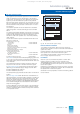
AS 235 K automation system
The AS 235 K automation system is the compact version of the
AS 235 system. Both systems use the same central unit
modules, interface modules and I/O modules. They also have
the same range of functions.
The AS 235 K system is fully operable on its own without any
extensions. Since the number of I/O modules which can be
plugged into the AS 235 K system is limited to 6, however, the
AS 235 K is usually used together with ES 100 K extension
systems (see page 3/21).
Basic system
The AS 235 K automation system is available for AC 230 V and
DC 24 V supply voltages. The basic system of the AS 235 K
automation system comprises:
• ES 902 subrack
– For AC 230 V C79451-A3260-A16
– For DC 24 V C79451-A3260-A17
each with
power supply subrack with slots for
power supply and alarm logic modules,
6 slots for I/O modules
1)
,
process connection panel for I/O modules
1 to 6, mounting plate with slots for
2 connector boards AF “Remote bus” and
slots for 2 bus converters UI,
power supply unit,
cable clamping rail with 10 clamps
• Power supply module SV1
For AS 235 K with AC 230 V:
– AC 230 V / DC 24 V C79451-A3260-A20
For AS 235 K with DC 24 V:
– DC 24 V / DC 24 V C79451-A3260-A25
• Power supply module SV2,
DC 24 V / DC 5 V C79451-Z1359-U9
• Alarm logic module 6DS1 901-8BA
• Bus terminator module C79458-L445-B20
• Flashing pulse generator 6DS1 922-8AA
• Central processing unit with
– Central processor module 6DS1 140-8AA
– EDC memory module 4000 Kbyte 6DS1 844-8FA
– Backup battery for memory module W79084-U1001-B2
– AS 235 system software, version G 6DS5 323-8AG
– Interface module for I/O bus 1 6DS1 312-8BB
1)
• Interface module for mini floppy disk unit 6DS1 326-8BB
• Interface module for operation channel 1 6DS1 330-8CA
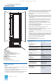
The subrack of the AS 235 K system corresponds to the ES 902
system and is 15
U
high. It is the supporting system for the other
components of the basic system, the bus components, and the
I/O modules.
The front of the subrack contains a process connection panel for
the process signal cables with Maxi-Termi-Point connections
(pins 2.4 mm x 0.8 mm). The rear of the process connection
panel is wired to the base plugs X2, i.e. the process interfaces
of the 6 I/O modules in the basic system.
Two power supply modules are used for the basic system:
• Power supply module SV1
One of the following modules is used depending on the
selected supply voltage for the AS 235 K:
– C79451-A3260-A20 (AC 230 V / DC 24 V) or
– C79451-A3260-A25 (DC 24 V / DC 24 V).
Both designs are equipped with 3 sockets via which 2 process
operation keyboards and a mini floppy disk unit can be pow-
ered with DC 24 V.
• Power supply module SV2
The power supply module SV2 (C79451-Z1359-U9) converts
DC 24 V into DC 5 V for the central processing unit and the
I/O bus interface modules.
1) If I/O slot 6 is used, the interface module for I/O bus 2 (B) is required in
addition. See AS 235 K functions for Ordering data.
The alarm logic module monitors the 24-V voltages
L
+ and
PM
,
the +5-V voltage and the optionally used signal inputs for tem-
perature monitoring, door contact and spare contact. Error mes-
sages via these signal inputs as well as further system mes-
sages trigger a flashing LED and a relay of the module at the
same time. This common alarm can be switched via this relay to
an external signalling lamp for another signalling device.
The flashing pulse generator has the following functions:
• Generation of a flashing signal which is required by the
I/O modules of the TELEPERM ME process control system for
alarm display. The flashing signal is fused in the flashing pulse
generator
• Lamp test for the fault display of the I/O modules which are
supplied with the flashing signal
• Electrical isolation of external time synchronization signals.
The AS 235 K can be synchronized using a minutes pulse.
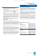
Communication
via CS 275 plant bus
I/O bus
MO MO
PBT, ST
DR
ES 100 K (max. 8)
SV
M
L
PA
E
13 I/O
modules
SV SV
M
L
PA
E
4(6) I/O
modules
B
T
ZE
UI1 UI2
AF1
AF2
GS
SV
M
L
PA
E
13 I/O
modules
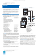
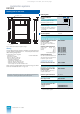
Fig. 3/7 AS 235 K automation system, system configuration
AF Connector board for remote bus
BT Flashing pulse generator
DR Printer
E Power supply unit
GS Basic system
ML Alarm logic module
MO Monitor
PA Process connection panel
PBT Process operation keyboard
ST Configuring keyboard
SV Power supply module
UI Bus converter
ZE Central unit
This catalog is out of date, see note on page 1