
User's Manual


Siemens PLT 111 · 1999
3/16
Automation systems
Extension cabinet
AS 235 H
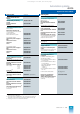
Ordering data Order No.
Options for AS 235 H basic
cabinet (continued)
Remote bus cable
See page 6/6
Option:
system cabinets
Parts kit for upgrading the
degree of protection of a
400-mm deep standard cabinet
from IP 10 to IP 20 (for former cab-
inets)
C79165-A3012-D90
Fan subassembly DC 24 V
(complete)
1)
1) Required with a cabinet power loss > 350 W and
a power loss > 150 W for an extension unit
Insulation kit/retrofitting kit for
AS 235 H basic cabinet with
degree of protection IP 10 or IP 20
• For installation below the basic
unit (initial use)
C79165-A3012-D204
• For installation below the basic
unit (retrofitting)
C79165-A3012-D225
• For installation below extension
unit EE2
C79165-A3012-D207
Insulation kit/retrofitting kit for AS
235 H basic cabinet with degree
of protection IP 54
• For installation below the basic
unit (initial use)
C79165-A3012-D204
• For installation below the basic
unit (retrofitting)
C79165-A3012-D226
• For installation below extension
unit EE2
C79165-A3012-D207
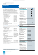
AS 235 H extension cabinet
Depending on the complexity of the automation function, the
AS 235 H can be increased up to max. 91 slots for I/O modules
by using up to 7 extension units.
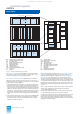
The extension units EE4 to EE7 are part of the extension cabinet.
They are connected to the central processing unit of an
AS 235 H system via 2 separate, redundant I/O buses 2 (B),
each with its own interface module for I/O bus (B).
An extension unit of the AS 235 H automation system consists of
a subrack with slots for 13 I/O modules, I/O bus comparator and
switchover module, and a DC 5 V power supply module.
When ordering the extension units it is possible to select whether
the extension unit EE4 is to be delivered on its own, together with
EE5, together with EE5, or together with EE6:
The following components are supplied:
• 1, 2, 3 or 4 subracks
with slots for 13 I/O modules each
– For wire-wrap system 6DS9 002-8BB
– For Maxi-Termi-Point system 6DS9 002-8BA
• 1, 2, 3 or 4 cable ducts, 2
U
high 6DS9 906-8AB
• 1, 2, 3 or 4 covers, 2
U
high 6DS9 906-8BB
• Cable set for power supply
– For EE4 6DS9 908-8GE
– For EE5 6DS9 908-8GF
– For EE6 6DS9 908-8GG
– For EE7 6DS9 908-8GH
• Cable set for I/O bus 2
– With EE4 on its own 6DS9 911-8GD
– With EE4 and EE5 6DS9 911-8GE
– With EE4, EE5 and EE6 6DS9 911-8GF
– With EE4, EE5, EE6 and EE7 6DS9 911-8GG
• Alarm logic module 3 6DS1 901-8AA
• 1 or 2 interface modules for I/O bus 2 6DS1 312-8BB
(slot: basic unit)
• 1, 2, 3 or 4 I/O bus comparators and 6DS1 144-8AA
switchover modules
• 1, 2, 3 or 4 upgrading sets with switched- C79451-A3117-D29
mode regulator DC 5 V (6DS1 006-8AA)
The system cabinets (see page 3/23 for further information) are
supplied with 2 cabinet lamps and test pushbuttons and consist
of the following components:
• Standard cabinet
– IP 20, 2200 x 900 x 400 6DS9 300-8AA
– IP 54, 2200 x 900 x 600 6DS9 310-8AB
– IP 20, 2200 x 900 x 600 6DS9 302-8AA
• Transport lugs (4 off) 6DS9 906-8CA
• Cable set for connection of cabinet lamp 6DS9 912-8AC
• Door contact with mounting parts and 6DS9 905-8CA
connection cables
• Cable duct, horizontal for I/O bus 6DS9 906-8PA
• Cable duct, vertical C79165-A3012-D72
• Thermostats, wired C79165-A3012-D86
• Cable with mounting parts C79165-A3012-D129
• Cable clamping rail C79165-A3012-D128
• Partition with cut-outs and mounting parts
– For standard cabinet IP 20, 400 mm deep 6DS9 906-8JB
– For standard cabinet IP 54 and IP 20, 6DS9 906-8MA
– 600 mm deep
The standard cabinet IP 54 with heat
exchanger is additionally supplied with
further components:
• Cable set for heat exchanger C79165-A3012-D19
• Cable for monitoring of heat exchanger C79195-A3828-H390
• Cable for connection of line filter to C79195-A3205-B94
motor supply terminals
Side panel or 2nd partition for the standard cabinets: see cabi-
net accessories on page 3/23.
This catalog is out of date, see note on page 1