
User's Manual


Siemens PLT 111 · 1999
1/4
TELEPERM M
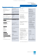
System data
Introduction
General system data
1)
Permissible ambient temperature
• Modules
– Operation
– Δt/h
– Δt/min
– Transport and storage
0 to 70 °C
Max. 10 K
Max. 0,5 K
-40 to +70 °C
• Cabinet (operation)
Cabinet ambient temperature at
1 m above cabinet base
0 to 40 °C
Reduction in specified temperature
above 1000 m above sea level
10 K/1000 m
Permissible humidity Operation Storage
– Annual average
– On 30 days/year
– On 60 days/year
Max. 75 % Max. 65 %
Max. 95 % –
– Max. 85 %
Condensation not permissible
Mechanical ambient conditions
Operation stress
(modules in subrack)
– 10 to 60 Hz
– 60 to 500 Hz
0.15 mm deflection
2 g acceleration
System cabinet
– 10 to 58 Hz
– 58 to 500 Hz
0.035 mm deflection
0.5 g acceleration
Transport stress
(modules in subrack)
– 5 to 8 Hz
– 8 to 500 Hz
7.5 mm deflection
2 g acceleration
Design, ear thing conditions
Potential difference between all
ground star points of distributed
systems
Max. 7 V
Insulation
According to VDE 0160
Protection class
Class l
Insulation of modules, clearances and
creepage distances from pin to pin or
from conductor to conductor
According to VDE 0110
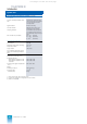
Signal data
(interface to field level)
• Binary signals
DC voltage Referred to
M
potential
Signal definition
– L (low)
– H (high)
Inputs Outputs
-30 to +4.5 V 0 to 2.5 V
+13 to +33 V L+ to
(L+ - 2.5 V)
Input currents
– Electronic transmitters
– Contacts
0.5 mA Typical values for
4 mA configuring
Output currents with DC 24 V
8.5 mA/100 mA/120 mA
Power signals
Max. 400 mA
Binary signal outputs
Short-circuit-proof and
overload-proof
1) Deviations possible in individual cases. Refer to technical data of individ-
ual components
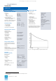
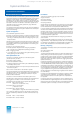
General system data
Fig. 1/2 Overvoltage resistance / dynamic destruction limit
• Analog signals
DC voltage
– Rated range of use
Referred to
M
Z
-10 to +10 V
-10 to 0 V
0 to +10 V
– Overflow range
– Input resistance
– Output loading capacity
-10.5 to +10.5 V
100 kΩ
1 mA
Direct current
– Rated range of use
– Overflow range
– Input resistance
– Rated output load
Referred to
M
0 to 20 mA or 4 to 20 mA
0 to 21 mA or 3.7 to 21 mA
12.5, 50 or 350 Ω
500 or 600 Ω
Analog signal outputs
Short-circuit-proof and over-
load-proof
Overvoltage resistance of binary and
analog inputs and outputs according
to IEC information 255-4 (Fig. 1/2)
Class II
This catalog is out of date, see note on page 1