
User's Manual


Siemens PLT 111 · 1999
3/12
Automation systems
Basic cabinet
AS 235 H
Redundant process I/Os
Some of the I/O modules are suitable for producing a redundant
process I/O area and for thus implementing an interruption-free
automation system.
When using corresponding software structures generated by
the user, it is possible to detect and signal the failure of an
I/O module, to disable the faulty module for system interven-
tions, and to continue data transfer via the redundant I/O mod-
ule. Thus faulty modules can be replaced without operation of
the individual loop.
Since the system redundancy ends at the I/O bus comparator
and switchover module (EAVU), the I/O modules which are
redundant to one another must be arranged in different exten-
sion units.
Power supply components
The DC 24 V power supply unit of the AS 235 H system com-
prises:
• Power supply subrack DC 24 V 6DS4 428-8AA
with slots for 2 bus converters UI,
24 automatic circuit-breakers,
2 supply diodes, 6 sockets for DC 24 V,
terminal and alarm strip,
overvoltage protection
• Connection distributor for 20-m local bus 6DS9 207-8AA
• Flashing pulse generator 6DS1 922-8AA
• Cabinet power supply terminals C79165-A3012-D73
for single supply
• Cabinet power supply terminals, extension set C79165-A3012-D74
for redundant power supply
The power supply subrack has separate fuses for the two partial
subsystems of the AS 235 H. The major functions of the power
supply subrack are:
• Redundant supply of DC 24 V in the basic cabinet or in the
basic and extension cabinets
• Fusing of DC 24 V for keyboards, mini floppy disk unit and heat
exchanger
• Separate supply of 2 bus converters with DC 24 V
• Combination of cabinet alarms for the basic unit
• Supply of an external minutes pulse
• Connection distributor for 20-m local bus (e.g. for central con-
figuring with PROGRAF AS+)
• Monitoring of central processing units and signal inputs of
basic and extension cabinets by the alarm logic modules
• Generation of a flashing pulse for I/O modules of the
TELEPERM ME process control system and the EAVU modules
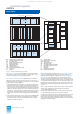
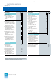
BE BA
EAVU
EEn
BE BA
EAVU
EEn+1
BA Binary output module
BE Binary input module
EAVU I/O bus comparator and
switchover module
EE Extension unit
Fig. 3/6 Example of redundancy with
I/O modules
(1-out-of-2 structure)
The flashing pulse generator has the following functions:
• Generation of a flashing signal which is required by the
I/O modules of the TELEPERM ME process control system
for alarm display (see Section 4 for modules).
The flashing pulse generator has two channels. The flashing
pulses of the two channels can be synchronized.
It provides a lamp test for the fault display of those I/O modules
which are supplied with the flashing signal (optional wiring).
• Electrical isolation of external time synchronization signals.
The AS 235 H can be synchronized using a minutes pulse.
Bus components
The TELEPERM M systems can communicate with one another
via the CS 275 plant bus up to distances of 20 m (local bus) or
4 km (remote bus). The local bus is redundant as standard. The
remote bus can be redundant as an option.
The central processing units of the two partial systems of the
AS 235 H are each connected to the CS 275 bus system via an
interface module N-AS. The interface modules handle all duties
connected with transmission, including occasional control of
data transfer. Only the interface module of the partial system
with the master function is active. Thus the AS 235 H system acts
on the bus as an individual participant despite the 2 connections
for modules N-AS on the bus.
Up to 9 participants can be interconnected as a local bus island
via the 20-m local bus (each bus converter Ul counts as 1 par-
ticipant). The total length of the connecting cables must not
exceed 20 m.
Interface modules for 20-m local bus of local bus participants
can be connected together at the front using cables 6DS8 201-
8.. . These cables are only provided with a plug at one end. They
must be connected 1:1 at the free end to the plug of the adjacent
local bus participant. If a cable is not yet connected there, a front
plug 6DS9 200-8AA is required in addition. The cable 6DS8 205-
8.. with 2 plugs can be used as an alternative to the combination
of cable 6DS8 201-8.. and front plug.
It is possible to connect a personal computer via the connection
distributor for 20-m local bus in the power distribution subrack.
If the connection distributor is not integrated into the local bus
via a connecting cable 6DS9 201-8FC, it must first be
connected to the interface module N-AS via a connecting cable
6DS9 201-8LC. Central configuring and feedback documenta-
tion of the AS 235 H can be carried out in conjunction with the
PROGRAF AS+ engineering tool (cf. Section 2).
The AS 235 H is connected to a single remote bus via the inter-
face connection unit. The AS 235 H can also be operated on a
redundant remote bus. 2 bus converters UI and 2 remote bus
connector boards AF are installed in this case. The interface
connection unit for redundant remote bus is required for the con-
nection to a redundant remote bus.
With the standard ordering configuration, an additional connec-
tion unit for a single or redundant remote bus can be selected
under “Power supply and bus components” in addition to the
power supply unit.
This catalog is out of date, see note on page 1