
User's Manual


Siemens PLT 111 · 1999
3/11
Automation systems
AS 235 H
Basic cabinet
Standard I/O devices
The standard I/O devices such as process monitor, process
operation keyboard, configuring keyboard, mini floppy disk unit,
logging printer and message printer are described in Section 5.
The interface modules for operation channel generate the RGB
signals for the process monitors. They also have three 20-mA
current loop interfaces to which the process operation keyboard
or the configuring keyboard and 2 printers (logging printer and
message printer) are connected.
No operation channel interface modules are essential if the
AS 235 H is always operated and configured centrally. However,
the use of an interface module is recommended for diagnostics.
The operation channel interface modules must be ordered
together with the standard devices.
In contrast to the AS 235 system, the process monitors, key-
boards and printers in the AS 235 H are not directly connected
to the operation channel interface module. The process motors
are connected to the operation channel interface modules of the
two partial systems via video relays. A video relay is assigned to
each operation channel. The video relays ensure that the con-
nected process monitors always display the same screen con-
tents. The process monitors are connected to the active partial
system when transferring to asynchronous operation. The video
relays are also connected to the synchronization modules for
this purpose.
The signal cables of the keyboards and printers are connected
to the operation channel interface modules of the two partial sys-
tems via distribution cables.
The keyboard and printer distributors as well as the video relays
are components of the parts set for operation channel switch-
over which belongs to the delivery of an operation channel.
An additional printer distributor is required if a second printer is
to be connected to an operation channel, and must be ordered
separately (option).
Possible connections and a summary of connecting cables: see
page 3/29 ff.
The combinations which can be ordered for the standard
I/O devices comprise:
• Interface module for operation channel 1 6DS1 330-8CA
(with redundant basic unit: 2 off)
• PBT 65 process operation keyboard
1)
6DS3 305-8BA
• Configuring keyboard 6DS3 303-8AA
with connecting cable, 1 m 6DS8 102-8AC
• Mini floppy disk unit with connecting cables for 6DS3 900-8AE
signal transmission and power supply, 3 m each
• Parts set for operation channel switchover C79165-A3012-D70
• In addition for operation channel 2:
– Interface module for operation channel 2 6DS1 330-8CA
– (with redundant basic unit: 2 off)
– Second PBT 65 process operation keyboard 6DS3 305-8BA
– Parts set for operation channel switchover C79165-A3012-D70
• One process monitor per operation channel as option:
– Process monitor SCM 2140-I
2)
6GF6100-1BV
Extension units
Depending on the complexity of the automation function, the
capacity of the AS 235 H can be increased up to max. 91 slots
for I/O modules by the addition of up to 7 extension units.
The extension units EE1 to EE3 are connected to the basic unit
via 2 separate, redundant I/O buses 1 (A). Each of these buses
is connected to the CPU of an AS 235 H partial system via a sep-
arate interface module for I/O bus 1 (A). These extension units
are fitted in the basic cabinet.
1) Order connecting cables for signal transmission and power supply in
addition, see page 5/5 (process operation keyboard)
2) Order connecting cables for signal transmission in addition,
see page 5/4 (process monitor)
Extension units EE4 to EE7 are fitted in the extension cabinet.
These are also connected to the CPU of an AS 235 H partial sys-
tem via 2 separate I/O buses 2 (B) which are redundant to one
another, each of which has its own interface module for
I/O bus 2 (B).
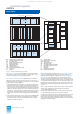
An extension unit of the AS 235 H automation system consists of
a subrack with slots for 13 I/O modules, I/O bus comparator and
switchover module, and a DC 5 V power supply module.
When ordering the extension units it is possible to select whether
the extension unit EE1 is to be delivered on its own, together with
EE2, or together with EE2 and EE3.
The following components are supplied:
• 1, 2 or 3 subracks
with slots for 13 I/O modules
– For wire-wrap system 6DS9 002-8BB
– For Maxi-Termi-Point system 6DS9 002-8BA
• 1, 2 or 3 cable ducts, 2
U
high 6DS9 906-8AB
• 1, 2 or 3 covers, 2
U
high 6DS9 906-8BB
• Cable set for power supply
– For EE1 6DS9 908-8GB
– For EE2 6DS9 908-8GC
– For EE3 6DS9 908-8GD
• Cable set for I/O bus, + 5 V, 0 V
– With EE1 on its own 6DS9 911-8GA
– With EE1 and EE2 6DS9 911-8GB
– With EE1, EE2 and EE3 6DS9 911-8GC
• 1, 2 or 3 I/O bus comparator and 6DS1 144-8AA
switchover modules
• 1, 2 or 3 upgrading sets with C79451-A3117-D29
switched-mode regulator DC 5 V (6DS1 006-8AA)
The extension units are supplied directly with DC 24 V from the
power supply subrack. Each extension unit is fused separately
with 16 A on the power supply subrack. The DC 5 V supply is
taken from the power supply module DC 5 V.
In addition to the I/O modules, the interface module for 20-mA
local bus N-V.24 can be inserted into the I/O slots of the
AS 235 H system. One interface module N-V.24 can be inserted
per interface module.
Accessories for the extension units: see Ordering data “Further
options for AS 235 H basic cabinet”.
I/O modules
The I/O modules are the process interface of the AS 235 H auto-
mation system. They comprise signal modules and function
modules, including calculation modules. See Section 4 for the
properties, functions and Ordering data of the I/O modules.
Up to 13 I/O modules can be inserted into each of the extension
units (max. 3) of the basic unit. Please observe the max. thermal
loading (see standard cabinets and accessories, page 3/23).
A further 52 I/O modules can be inserted into an additional
extension cabinet with up to 4 extension units, thus enabling a
total of 91 I/O modules per AS 235 H system.
One ES 100 K extension system can additionally be connected
per I/O bus 1.
During planning it should be noted that the 16 A with which each
extension unit is fused must not be exceeded.
The I/O modules can be supplied coded, inserted and with
labelled slots. Arrangement, designation and connection dia-
grams (including address data) are required from the orderer.
• Coding, inserting and labelling 6DS5 705-8AA
for 1 I/O module
This catalog is out of date, see note on page 1