
User's Manual


Siemens PLT 111 · 1999
3/10
Automation systems
Basic cabinet
AS 235 H
The memory module with
Error Detection and Correction
EDC
can correct a 1-bit error when reading, and eliminate it in the
memory cell together with the system software.
The interface module for I/O bus establishes the connection
between the 8-bit central bus and the I/O bus. One or two of
these modules can be plugged into the basic unit of each partial
system of the AS 235 H system:
• The interface module for I/O bus 1 (A) is essential for partial
systems I and II and is included in the delivery of the basic unit.
Each of the two CPUs operating with synchronous clocks is
connected to the I/O bus comparator and switchover modules
(EAVU) of the basic cabinet via its own interface module and
own I/O bus 1 (A). Both the two interface modules and the two
I/O buses 1 (A) are redundant to one another. This enables
two-channel, clock-synchronous triggering of the EAVU mod-
ules.
• The interface modules for I/O bus 2 (B) must be ordered addi-
tionally (one module for each partial system). The interface
modules are only required if an extension cabinet is used in
addition to the basic cabinet.
AS 235 H basic unit
Power supply subrack
AS 235 H basic unit AS 235 H extension cabinet
EE4
EE5
EE6
EE1
EE2
EE3
GE
AS 235 H
SES
V1 V2 ST2 AV
UI
Bus A
UI
Bus B
EE7
EAVU
EAVU
BT
Automatic circuit-breakers
ST1
ML
1
ML
2
ML
3
VD
1
VD
2
Partial system I Partial system II
SV SV
Backup module
DC 24 V
N-AS
N-AS
AMD
AMD
BK2
BK2
EAB2
EAB2
BK1
BK1
EAB1
EAB1
CPU
CPU
RAM
RAM
BAB/DG
BAB/DG
SB
SB
VKB
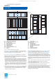
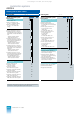
Fig. 3/5 AS 235 H automation system, design
AMD Interface module for mini floppy disk unit
AV Connection distributor for 20-m local bus
BAB Bus terminator module
BK Interface module for operation channel
BT Flashing pulse generator
CPU Central processor module
DG Diagnostics interface
EAB Interface module for I/O bus
EAVU I/O bus comparator and switchover module
EE Extension unit
GE Basic unit
ML Alarm logic module
N-AS Interface module for 20-m local bus
RAM Memory module
SB Synchronization module
SES Power supply subrack
ST 24 V sockets for connection of keyboards
SV Power supply module DC 24 V / DC 5 V
UI Bus converter
V Supply diode
VD Diode module for linking signals
VKB Comparator/coupling module
Each of the two partial systems has a synchronization module.
The two modules are redundant to one another and linked
together without feedback. Together with the comparator/cou-
pling module they constitute the central components of the
AS 235 H system responsible for the control, coordination and
monitoring of the two partial systems. The synchronization mod-
ule is also required for operation of a non-redundant basic unit.
Depending on the configuration of the automation system, the
power supply subrack is equipped with one or more alarm logic
modules:
• Alarm logic module ML1 (basic cabinet with 1 partial system)
• Alarm logic modules ML1 and ML2 (basic cabinet with
2 redundant partial systems)
• Alarm logic modules ML1, ML2 and ML3 (basic cabinet with
2 redundant partial systems and extension cabinet).
The alarm logic models monitor the central processing units and
the optionally used signal inputs for temperature monitoring,
door contact, fan contact and spare contact. In the event of a
fault, the cabinet lamps on the basic and extension cabinets are
triggered via these contacts.
This catalog is out of date, see note on page 1