
User's Manual


Siemens PLT 111 · 1999
3/9
Automation systems
AS 235 H
Basic cabinet
AS 235 H automation system
The AS 235 H automation system is the high-availability cabinet
version of the AS 235 range. In contrast to the simple cabinet
version, the AS 235 H is of redundant design and operates
according to the 1-out-of-2 principle.
It is possible to implement interruption-free operation with a fully-
redundant basic unit, the I/O bus (redundant as standard), the
I/O bus comparator and switchover modules, and redundant
I/O modules.
The AS 235 H must be ordered in the form of 2 separate ordering
units: the basic cabinet and the extension cabinet:
The basic cabinet is the main component of the AS 235 H auto-
mation system. It contains all components required for the
AS 235 H system to function and is fitted with up to 3 extension
units. It can therefore also be used on its own without an exten-
sion cabinet.
The extension cabinet is used to increase the number of slots
available for I/O modules. It can only be operated in conjunction
with the basic cabinet and can be equipped with up to 4 exten-
sion units. Together with the extension cabinet it is possible to
increase the number of slots for I/O modules in the basic cabinet
(39) to a total of 91.
Basic cabinet
The basic cabinet consists of the following main components:
Basic unit
The basic unit of the AS 235 H automation system consists of
2 identical partial systems which are designed symmetrically
and which operate in synchronism and redundant to one
another. A non-redundant basic unit can also be ordered.
The redundant basic unit comprises:
• Subrack 6DS9 027-8AB
• Power supply subrack DC 24 V / DC 5 V 6DS4 432-8AA
• 2 power supply modules C79451-Z1359-U9
DC 24 V / DC 5 V
• Backup module DC 24 V C79451-A3125-B227
• Central processing units ZE I and ZE II with
– 2 central processor modules 6DS1 141-8AA
– 2 EDC memory modules 4000 Kbyte 6DS1 844-8FA
– 2 backup batteries for memory module W79084-U1001-B2
– AS 235 system software, version G 6DS5 323-8AG
– 2 interface modules for I/O bus 1 6DS1 312-8BB
– 2 synchronization modules 6DS1 143-8AA
– Comparator/coupling module 6DS1 142-8AA
• 2 interface modules 6DS1 326-8BB
for mini floppy disk unit
• 2 alarm logic modules
1)
6DS1 901-8AA
• 2 bus terminator modules C79458-L445-B20
• Cable set 6DS9 908-8GA
• Cable duct, rear 6DS9 906-8AA
• Cable duct, horizontal (rear) 6DS9 906-8AB
• Cable duct, horizontal (front) 6DS9 906-8TA
• Cover with wiring duct 6DS9 927-8AA
The non-redundant basic unit comprises:
• Subrack 6DS9 027-8AB
• Power supply subrack DC 24 V / DC 5 V 6DS4 432-8AA
• Power supply module DC 24 V / DC 5 V C79451-Z1359-U9
• Backup module DC 24 V C79451-A3125-B227
More information on the topic of redundancy can also be found in
Section 2, page 2/3 “Redundancy with AS 235 H”
1) Can be inserted into power supply subrack
• Central processing units ZE I with
– 1 central processor module 6DS1 141-8AA
– 1 EDC memory module 4000 Kbyte 6DS1 844-8FA
– 1 backup battery for memory module W79084-U1001-B2
– AS 235 system software, version G 6DS5 323-8AG
– 1 interface module for I/O bus 1 6DS1 312-8BB
– 1 synchronization modules 6DS1 143-8AA
• 1 interface module for mini floppy disk unit 6DS1 326-8BB
• 1 alarm logic module
1)
6DS1 901-8AA
• 1 bus terminator module C79458-L445-B20
• Cable set 6DS9 908-8GA
• Cable duct, rear 6DS9 906-8AA
• Cable duct, horizontal (rear) 6DS9 906-8AB
• Cable duct, horizontal (front) 6DS9 906-8TA
• Cover with wiring duct 6DS9 927-8AA
The subrack for the central modules of the AS 235 H corre-
sponds to the ES 902 packaging system and is 10
U
high. It is
the supporting system for the two central processing units, the
comparator/coupling module and the interface modules for mini
floppy disk unit, operation channel and 20-m local bus. The
3-
U
high power supply subrack 6DS4 432-8AA accommodates
the power supply modules required for the basic unit as well as
the backup module.
The power supply module C79451-Z1359-U9 is used to supply
the basic unit with DC 5 V. Each AS 235 H partial system is sup-
plied from its own power supply module. The backup module
compensates brief voltage dips in the DC 24 V supply.
The central processor modules of the AS 235 H basically corre-
spond to those of the AS 235 system. The required clocks are no
longer generated on the module itself but are supplied by the
synchronization module.
SV
SV
Communication
via CS 275 plant bus
I/O bus
MO MO
PBT, ST
DR
(max. 7)
13 I/O
modules
GE
EE
ZE II
ZE I
I/O bus
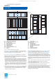
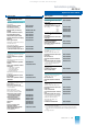
Fig. 3/4 AS 235 H automation system, system configuration
DR Printer
EE Extension unit
GE Basic unit
MO Monitor
PBT Process operation keyboard
ST Configuring keyboard
SV Power supply module
ZE Central unit
This catalog is out of date, see note on page 1