
User's Manual

Siemens PLT 111 · 1999
3/6
Automation systems
Ordering data for basic cabinet
AS 235
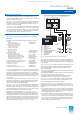
With the standard ordering configuration, an additional connec-
tion unit for a single or redundant remote bus can be selected
under “Power supply and bus components” in addition to the
power supply unit. The connection unit comprises:
• Interface module for 20-m local bus N-AS 6DS1 223-8AC
• Bus converter UI 6DS4 400-8AB
(2 x with redundant remote bus)
• Connector board AF “Remote bus” 6DS9 203-8DA
(2 x with redundant remote bus)
• For single remote bus:
Connecting cable with 3 plugs for connection 6DS8 204-8LC
of N-AS to bus converter 1 and
connection distributor for 20-m local bus
• For redundant remote bus:
Connecting cable with 4 plugs for connection 6DS9 201-8CA
of N-AS to bus converters 1 and 2
and connection distributor for 20-m local bus
The appropriate remote bus cable is required in addition to an
interface connection unit for single or redundant remote bus.
This cable is connected to the connector board AF and links the
individual participants together at distances up to 4 km.
Ordering data for remote bus cable: see Section 6.
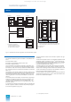
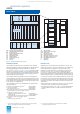
System cabinets
The system cabinets (see page 3/23 for further information) are
supplied with 2 cabinet lamps and test pushbuttons and consist
of the following components:
• Standard cabinet
– IP 20, 2200 x 900 x 400 6DS9 300-8AA
– IP 54, 2200 x 900 x 600 6DS9 310-8AB
– IP 20, 2200 x 900 x 600 6DS9 302-8AA
• Transport lugs (4 off) 6DS9 906-8CA
• Cable set for connection of cabinet lamp 6DS9 912-8AA
• Door contact with mounting parts and C79165-A3012-D83
connection cables
• Cable duct, horizontal, for I/O bus 6DS9 906-8PA
• Cable duct, vertical C79165-A3012-D51
• Parts kit (screen board) C79165-A3012-D41
• Thermostats, wired C79165-A3012-D81
• Cable with mounting parts C79165-A3012-D129
• Cable clamping rail C79165-A3012-D128
The standard cabinet IP 54 with heat exchanger is supplied with
the following additional components:
• Power distribution subrack AC 230 V 6DS4 408-8AA
with line filter
• Cable for monitoring the C79195-A3828-H230
heat exchanger
• Cable for connection of line filter C79195-A3205-B93
to motor supply terminals
Side panels or partitions for the standard cabinets: see cabinet
accessories on page 3/23.
System documentation
German or English system documentation can be ordered with
the AS 235 basic cabinet. The documentation comprises:
• Manuals
– “AS 235 automation system” C79000-G8000-C295
– “Function modules”, volumes 1 and 2 C79000-G8000-C30
– “Signal modules” C79000-G8000-C31
– “Coupling and calculation modules” C79000-G8000-C32
– “CS 275 bus system” C79000-G8000-C6
• Description “AS 235, AS 235 H and AS 235 K C79000-G8000-C416
automation systems, version G”,
volumes 1 to 3
• Manual “Notes and guidelines for C79000-G8000-C417
planning, installation and operation”
In the English system documentation, the center block of the
individual Order Nos. is replaced by “.....-G8076-...”.
• AS 235 / AS 235 H / AS 235 K table pamphlet, C79000-N8000-C1
German, order separately if required
.
Also refer to the ordering instructions in the appendix (page 8/2) with
information on ordering complete systems and options.
Ordering data
AS 235 automation system,
basic cabinet
6DS2 124- -
Basic unit
• Without basic unit 0
• Basic unit 4 Mbyte,
wire-wrap system
7
• Basic unit 4 Mbyte,
Maxi-Termi-Point system
8
Standard I/O devices
• Without standard I/O devices X
• For operation channel 1:
process operation/configuring
keyboards, mini floppy disk unit
– Without process monitor
– With process monitor
A
M
• Operation channel 2: 2 process
oper. keyboards, config. key-
board and mini floppy disk unit
– Without process monitor
– With 2 process monitors for
operation channels 1 and 2
C
N
Option:
extension units
• Without extension unit X
• Extension unit EE1,
wire-wrap system
A
• Extension unit EE1,
Maxi-Termi-Point system
B
• Extension units EE1
and EE2,
wire-wrap system
C
• Extension units EE1
and EE2,
Maxi-Termi-Point system
D
• Extension units EE1,
EE2 and EE3,
wire-wrap system
E
• Extension units EE1,
EE2 and EE3,
Maxi-Termi-Point system
F
Option: power supply and bus
components
• Without components 0
• Power supply unit DC 24 V
for single supply
1
• Power supply unit DC 24 V
for single supply and
connection unit for remote bus
2
• Power supply unit DC 24 V
for single supply and
connection unit for redundant
remote bus
3
Option:
system cabinets
• Without cabinet 0
• Standard cabinet, 400 mm
deep, degree of protection
IP 20, without heat exchanger
1
• Standard cabinet, 600 mm
deep, degree of protection
IP 54, with heat exchanger
2
• Standard cabinet, 600 mm
deep, degree of protection
IP 20, without heat exchanger
3
Option:
System documentation
• Without system documentation 0 X
• German documentation 0 D
• English documentation 0 E
O
r
d
er
N
o.
This catalog is out of date, see note on page 1