
User's Manual

Siemens PLT 111 · 1999
3/5
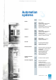
Automation systems
AS 235
Basic cabinet
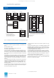
When ordering the extension units it is possible to select whether
the extension unit EE1 is to be delivered on its own, together with
EE2, or together with EE2 and EE3. The following components
are supplied:
• 1, 2 or 3 subracks
with slots for 14 I/O modules each
– For wire-wrap system 6DS9 002-8BB
– For Maxi-Termi-Point system 6DS9 002-8BA
• 1, 2 or 3 cable ducts, 2
U
high 6DS9 906-8AB
• 1, 2 or 3 covers, 2
U
high 6DS9 906-8BB
• Cable set for power supply
– For EE1 on its own 6DS9 908-8CA
– For EE1 (combined with further EE) 6DS9 908-8CB
– For EE2 6DS9 908-8CC
– For EE3 6DS9 908-8CD
• Cable set for I/O bus, + 5 V, 0 V
– With EE1 on its own 6DS9 911-8FA
– With EE1 and EE2 6DS9 911-8FB
– With EE1, EE2 and EE3 6DS9 911-8FC
The extension units are supplied directly with DC 24 V from the
power distribution subrack. Each extension unit is fused sepa-
rately with 16 A on the power distribution subrack. The DC 5 V
supply for the I/O bus is taken from the power supply module
SV2 (C79451-Z1359-U9) in the basic unit and applied via the
cable set 6DS9 911-8.. .
In addition to the I/O modules, max. 2 interface modules for 20-m
local bus N-V.24 can be inserted into the I/O slots of the AS 235
system.
Accessories for the extension units: see Ordering data “Further
options for AS 235 basic cabinet”.
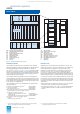
I/O modules
The I/O modules are the process interface of the AS 235 auto-
mation system. They comprise signal modules and function
modules, including calculation modules. See Section 4 for the
properties, functions and Ordering data of the I/O modules.
The basic unit of the AS 235 system has 6 slots for I/O modules.
A further 42 I/O modules can be accommodated in the basic
cabinet by inserting into 3 extension units with 14 slots each.
A further 42 I/O modules can be inserted into an additional
extension cabinet with up to 3 extension units, thus enabling a
total of 90 I/O modules per AS 235 system.
One ES 100 K extension system can additionally be connected
per I/O bus.
During planning it should be noted that the 16 A with which each
extension unit is fused must not be exceeded.
The I/O modules can be supplied coded, inserted and with
labelled slots. Arrangement, designation and connection dia-
grams (including address data) are required from the orderer.
• Coding, inserting and labelling 6DS5 705-8AA
for 1 I/O module
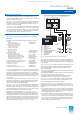
Power supply components
The standard DC 24 V power supply unit of the AS 235 system
comprises:
• Power distribution subrack for DC 24 V 6DS4 407-8CA
with slots for 2 bus converters UI,
8 automatic circuit-breakers,
1 supply diode, terminal and alarm strip,
overvoltage protection
• Connection distributor for 20-m local bus 6DS9 207-8AA
• Flashing pulse generator 6DS1 922-8AA
• 3 cabinet power supply terminals C79165-A3012-D73
The power distribution subrack has separate automatic circuit-
breakers for the basic unit and up to 6 extension units in the
basic cabinet and the extension cabinets. The major functions of
the power distribution subrack are:
• Supply of DC 24 V to a cabinet or a cabinet group
• Fusing of L+ and PM for the extension units and 24-V heat
exchanger
• Separate supply of 2 bus converters with DC 24 V
• Combination of alarms as well as triggering of cabinet lamps
and the cabinet row lamp (AS 235 H)
• Combination of cabinet lamps for the basic unit
• Generation of a flashing pulse for I/O modules of the
TELEPERM ME process control system
• Supply of an external minutes pulse
• Connection distributor for 20-m local bus (e.g. for central con-
figuring with PROGRAF AS+).
The DC 24 V supply is not redundant as standard. However, the
power distribution subrack is prepared for a redundant supply of
DC 24 V. A redundant supply of DC 24 V into the cabinet is also
possible by installing a second supply diode and an extension
set consisting of capacitor, a cable set and 2 cabinet supply ter-
minals. These must be ordered separately.
The flashing pulse generator has 3 functions:
• Generation of a flashing signal which is required by the I/O
modules of the TELEPERM ME process control system for
alarm display (see Section 4 for modules)
• Signal lamp test using the LT key on the front panel (wiring
optional)
• Electrical isolation of external time synchronization signals. The
AS 235 can be synchronized using a minutes pulse.
Bus components
The TELEPERM M systems can communicate with one another
via the CS 275 plant bus up to distances of 20 m (local bus) or
4 km (remote bus).
The local bus is redundant as standard. The remote bus can be
redundant as an option.
Up to 9 participants can be interconnected as a local bus island
via the 20-m local bus (each bus converter Ul counts as 1 par-
ticipant). The total length of the connecting cables must not
exceed 20 m.
Interface modules for 20-m local bus (e.g. N-AS and N-V.24) of
local bus participants can be connected together at the front
using cables 6DS8 201-8.. . These cables are only provided with
a plug at one end. They must be connected 1:1 at the free end
to the plug of the adjacent local bus participant. If a cable is not
yet connected there, a front plug 6DS9 200-8AA is required in
addition. The cable 6DS8 205-8.. with 2 plugs can be used as an
alternative to the combination of cable 6DS8 201-8.. and front
plug.
It is possible to connect a personal computer via the connection
distributor for 20-m local bus in the power distribution subrack.
It must first be integrated into the local bus via a cable connector
6DS8 201-8.. or, in the case of a remote bus connection, via a
cable 6DS8 204-8LC / 6DS9 201-8CA (see connection unit).
Central configuring and feedback documentation of the AS 235
can be carried out in conjunction with the PROGRAF AS+ engi-
neering tool (cf. Section 2).
The AS 235 is connected to a single remote bus via the interface
connection unit.
The AS 235 can also be operated on a redundant remote bus.
2 bus converters UI and 2 remote bus connector boards AF are
installed in this case. The interface connection unit for redundant
remote bus is required for the connection to a redundant remote
bus.
This catalog is out of date, see note on page 1