
User's Manual

Siemens PLT 111 · 1999
3/4
Automation systems
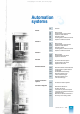
Basic cabinet
AS 235
Standard I/O devices
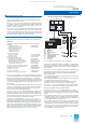
The standard I/O devices such as process monitor, process
operation keyboard, configuring keyboard, mini floppy disk unit
and logging/message printers are described in Section 5.
The interface modules for operation channel generate the RGB
signals for the process monitors. They also have three 20-mA
current loop interfaces to which the process operation keyboard
or the configuring keyboard and 2 printers (logging and mes-
sage printers) can be connected.
The interface module for operation channel 1 belongs to the
scope of delivery of the basic unit and is always required. A sec-
ond interface module is only required if 2 operating consoles are
to be used via which operation and monitoring or configuring are
to be carried out independently.
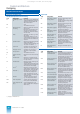
The combinations which can be ordered for the standard I/O
devices comprise:
• PBT 65 process operation keyboard
1)
6DS3 305-8BA
• Configuring keyboard 6DS3 303-8AA
with connecting cable, 1 m 6DS8 102-8AC
• Mini floppy disk unit with connecting cables for 6DS3 900-8AE
signal transmission and power supply, 3 m each
• In addition for operation channel 2:
– Interface module for operation channel 2 6DS1 330-8CA
– 3 cable clamps C79363-A3006-B10
– Second PBT 65 process operation keyboard 6DS3 305-8BA
• One process monitor per operation channel
as option:
– Process monitor SCM 2140-I
2)
6GF6100-1BV
1) Order connecting cables for signal transmission and power supply in
addition, see page 5/5 (process operation keyboard)
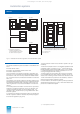
SV2
AS 235 basic unit
Power distribution subrack
AS 235 basic cabinet AS 235 extension cabinet
EE4
EE5
EE6
EE1
EE2
EE3
GE
AS 235
SVZ DC24V
V1 V2 SI AV
UI
Bus A
UI
Bus B
123456
ML1
ML2
BK2
EAB2
BK1
EAB1
AMD
N-AS
CPU
RAM
BAB/DG
SSO
Slots
for I/O modules
SV1
BT
SV2
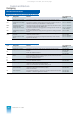
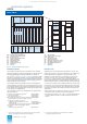
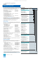
Fig. 3/3 AS 235 automation system, design
AMD Interface module for mini floppy disk unit
AV Connection distributor for 20-m local bus
BAB Bus terminator module
BK Interface module for operation channel
BT Flashing pulse generator
CPU Central processor module
DG Diagnostics interface
EAB Interface module for I/O bus
EE Extension unit
GE Basic unit
ML Alarm logic module
N-AS Interface module for 20-m local bus
RAM Memory module
SI Automatic circuit-breaker
SSO Special interface, not used
SV1 Power supply module DC 24 V / DC 24 V
SV2 Power supply module DC 24 V / DC 5 V
SVZ Power distribution subrack DC 24 V
UI Bus converter
V Supply diode
Extension units
Depending on the complexity of the automation function, the
capacity of the basic unit for I/O modules can be increased up
to max. 90 slots by the addition of up to 6 extension units.
Extension units EE1 to EE3 are connected to the central pro-
cessing unit via I/O bus 1 (A) and the interface module for
I/O bus 1 (A). These extension units are accommodated in the
basic cabinet. Extension units EE4 to EE6 are components of the
extension cabinet and thus connected to the central processing
unit via I/O bus 2 (B) and the interface module for I/O bus 2 (B).
An extension unit of the AS 235 automation system consists of a
6-
U
high subrack with slots for 14 I/O modules (each 2 standard
slots wide). 2 subracks with different process connections are
available for
• Maxi-Termi-Point connections, pins 0.8 mm x 2.4 mm (recom-
mended for direct connection of process cables) or
• wire-wrap connections, pins 1 mm x 1 mm (recommended for
process cable connection via SAE cabinet connection ele-
ments).
2) Order connecting cables for signal transmission in addition,
see page 5/4 (process monitor)
This catalog is out of date, see note on page 1