
User's Manual

Siemens PLT 111 · 1999
3/3
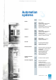
Automation systems
AS 235
Basic cabinet
AS 235 automation system
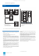
The AS 235 automation system is the cabinet version of the
range. It can be ordered in the form of two ordering units: basic
cabinet and extension cabinet:
The basic cabinet is the main component of the AS 235 automa-
tion system. It contains all components required for the AS 235
system to function. It can therefore also be used on its own, i.e.
without an extension cabinet.
The extension cabinet increases the number of slots for I/O mod-
ules. It can only be operated in conjunction with the basic cabi-
net with up to 3 extension units. When using an extension cabi-
net it is possible to increase the number of slots for I/O modules
in the basic cabinet (48) up to a maximum of 90.
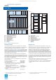
Basic cabinet
The basic cabinet consists of the following main components:
Basic unit
The basic unit of the AS 235 automation system consists of:
• Subrack
– For wire-wrap system 6DS9 026-8AB
– For Maxi-Termi-Point system 6DS9 026-8AA
• Power supply subrack with
– Slots for power supply and
logic modules and
– 6 slots for I/O modules
• Power supply module
– DC 24 V / DC 24 V C79451-A3260-A25
– DC 24 V / DC 5 V C79451-Z1359-U9
• Alarm logic module 6DS1 901-8BA
• Central processing unit with
– Central processor module 6DS1 140-8AA
– EDC memory module 4000 Kbyte 6DS1 844-8FA
– Backup battery for memory module W79084-U1001-B2
– AS 235 system software, version G 6DS5 323-8AG
– Interface module for I/O bus 1 6DS1 312-8BB
• Interface module for mini floppy disk unit 6DS1 326-8BB
• Interface module for operation channel 1 6DS1 330-8CA
• Bus terminator module C79458-L445-B20
• Cable duct, 2
U
high 6DS9 906-8AB
• Cover with wiring duct 6DS9 927-8AA
• Cable set for power supply and alarms 6DS9 908-8CA
The subrack for the basic unit of the AS 235 system corresponds
to the ES 902 system and is 10
U
high. It is the supporting sys-
tem for the other components of the basic unit, the interface
modules for the local bus, and the I/O modules. The process sig-
nal lines for the 6 I/O modules are connected to the rear, the plug
connectors are equipped with wire-wrap or Multi-Termi-Point
connections.
If the process signal cables leading to I/O slot 6 are to the con-
nected in the cabinets also using the Maxi-Termi-Point system,
conversion is necessary using SAE cabinet connection ele-
ments. These must be ordered separately.
The power supply module C79451-A3260-A25 is used to supply
the basic unit with DC 24 V. The DC 24 V supply voltage is fil-
tered and additionally fused on this module. Two process oper-
ation keyboards and a mini floppy disk unit can be powered with
DC 24 V via 3 sockets on the front of the module.
The basic unit is equipped with 1 or 2 alarm logic modules
depending on the configuration of the automation system. The
alarm logic module ML1 is assigned to the basic cabinet. The
alarm logic module ML2 is only required if the AS 235 system
consists of a basic cabinet and an extension cabinet and has a
basic unit with wire-wrap pins. In the case of the basic unit with
Maxi-Termi-Point system, the tasks of the alarm logic module
ML2 are handled by the interface module for I/O bus 2.
The alarm logic modules monitor the voltages
L
+,
PM
(DC 24 V
each) and +5 V as well as the I & C signals for overtemperature,
door contacts, fan contacts and spare contacts, and trigger the
current lamps.
The central processor is especially tailored to the processing of
closed-loop and open-loop control tasks and to the TML pro-
gramming language. It divides the RAM and differentiates
access operations to
• the 1-Mbyte system RAM with battery backup for all fixed sys-
tem data and programs,
• the 4000-Kbyte RAM with battery backup for all user programs
and data and for variable system data, and
• the transfer memories of the interface modules for I/O bus,
operation channel, mini floppy disk unit and local bus.
The memory module with
Error Detection and Correction
EDC
can correct a 1-bit error when reading, and eliminate it in the
memory cell together with the system software.
The interface module for I/O bus establishes the connection
between the 8-bit central unit bus and the I/O bus. One or two of
these modules can be plugged into the basic unit of the AS 235
system:
• The interface module for I/O bus 1 (A) supplies the I/O modules
plugged into slots 1 to 5 of the basic unit and the 3 extension
units of the basic cabinet. It is always required, and belongs to
the standard delivery of the basic unit.
• The interface module for I/O bus 2 (B) must the ordered as an
option. It connects slot 6 for I/O modules in the basic unit and
the 3 extension units of the extension cabinet to the central pro-
cessing unit via I/O bus 2 (B). It is therefore only required if slot
6 in the basic unit is to be used, or if an extension cabinet is
used in addition to the basic cabinet.
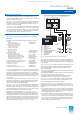
SV SV
M
L
6 I/O
modules
ZE
Communication
via CS 275 plant bus
I/O bus
MO MO
PBT, ST
DR
(max. 6)
14 I/O
modules
GE
EE
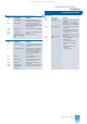
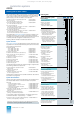
Fig. 3/2 AS 235 automation system, system configuration
DR Printer
EE Extension unit
GE Basic unit
ML Alarm logic module
MO Monitor
PBT Process operation keyboard
ST Configuring keyboard
SV Power supply module
UI Bus converter
ZE Central unit
This catalog is out of date, see note on page 1