
User's Manual


Siemens PLT 111 · 1999
2/6
System architecture
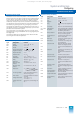
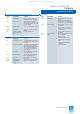
Standard function blocks
Configuring
Blocks for processing with
standardized operation and monitoring
Type Designation Function
R
RN
Closed-loop control-
ler
PID control, e.g. for disturbance
variable feedforward, tracking of
setpoint and manipulated vari-
able, limit formation
As R,
with additional functions
M
Measured-value
monitoring
Monitors a measured value for 3
pairs of limits
Extension of a closed-loop con-
trol block for limit monitoring
Limitation of measured value at
the error limits
V
Ratio Generation of a ratio, e.g. with a
ratio control
Proportional adjuster, e.g. with
synchronization control or to influ-
ence the command variable in a
cascade
B
Operation block Display of analog values (internal
result of calculations, ...)
Access to analog and binary val-
ues (input of constants, ...)
S
Control unit Operation and monitoring of a
sequence in process plants
G
GK
Subgroup control
Group control
Operation and monitoring of
sequences in power plants
As G,
with additional functions
A
Output for binary
data
Display of and access to a binary
value
F
Window block Display of 5 measured values;
each of the 5 values is monitored
for a pair of limits
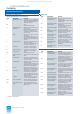
FN
Window block Display and limit monitoring of 5
measured values;
input of 5 pairs of limits each with
hysteresis as well as 5 ranges for
the measured value display
T
Trend
1)
1) Displays in PROGRAF AS+
Display of the trend of 2 mea-
sured values as a bargraph; time
base between 1.625 s and 36 h
SR
Recorder
1)
Summary of up to 4 series of
measurements, displayed on
screen as dashed-line curves;
4 pairs of limits for monitoring the
measured values
C
Selector To switch over binary signals,
e.g. manual/automatic mode
PKM
Alarm acquisition Acquires planned alarms from
binary input module/GB block
PKF
Alarm sequence dis-
play
1)
Output of PKM alarms; new
alarms of PKM blocks, display of
alarm history
Data blocks
Blocks for signal exchange via CS 275
Type Designation Function
GA
Data block for global
analog values
Storage of 256 analog values
with error 10
-9
;
storage of process image, histor-
ical values etc.
GB
Data block for global
binary values
Storage and scanning of 256
binary values;
especially for binary process
inputs and outputs
GM
Data block for global
flags
Storage and scanning of 256
internal binary statuses
GT
Data block for global
times (timer)
Storage and generation of times/
timers for execution of time-
dependent functions
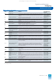
FA
Data field block for
analog values
Storage of internal/external ana-
log values with error 10
-9
;
especially for internal results
FSA
Data field block for
analog values
Storage of internal/external ana-
log values with error 10
-4
; espe-
cially for internal results
FB
Data field block for
binary data
Storage of internal/external
binary values; extension of GB/
GM blocks
FC
Data field block for
characters
Storage of characters (texts)
Type
Designation Function
AKS
Analog coupling and
transmitter block
Transmission of up to 28 analog
values and abbreviated time
(minutes and seconds) from an
AS 235 system to a max. of 6 or
32 receivers (AKE blocks)
AKE
Analog coupling and
receiver block
Reception of up to 28 analog val-
ues via the CS 275 from the data
set of an MKS block of another
bus participant
BKS
Binary coupling and
transmitter block
Transmission of up to 128 binary
signals and abbreviated time
from an AS 235 to a max. of 6 or
32 receivers (BKE blocks)
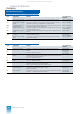
BKE
Binary coupling and
receiver block
Reception of up to 128 binary val-
ues via the CS 275 from the data
set of a BKS block of another bus
participant
ZKS
Character coupling
and transmitter block
Transmission of up to four S16
strings from an AS 235 to up to 6
or 32 receivers (ZKE blocks)
ZKE
Character coupling
and receiver block
Reception of up to four S16
strings from another AS system
MKS
Alarm coupling and
transmitter block
Transition of 32 binary signals as
alarms (with the time a signal
changes from 0
→1 or 1→ 0) to
other bus participants
MKE
Alarm coupling and
receiver block
Reception of 32 binary signals of
an MKS block and the time of
transmission sent by another bus
participant via the CS 275
SKS
Status coupling and
transmitter block
Transfer of status information to
higher-level systems (operator
system, computer)
PLPS
Reading and writing
of parameters
Reading or writing of up to 20
parameters from a bus-coupled
AS 235 system
This catalog is out of date, see note on page 1