
User's Manual


Siemens PLT 111 · 1999
2/5
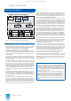
System architecture
Configuring
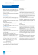
Standard function blocks
Standard function blocks
Dedicated function blocks are present in the automation sys-
tems to solve the control tasks. These are the so-called standard
function blocks. The AS 235, AS 235 H and AS 235 K systems
have the same standard function blocks for data acquisition,
closed-loop and open-loop control, calculation and monitoring.
The standard function blocks present in the system software are
activated by engineering tools using configuring instructions.
The blocks are combined into an automation structure which is
processed cyclically, and sometimes acyclically, by the central
processor of the automation system.
The configuration of the automation structure is us
ually gener-
ated graphically using the PROGRAF AS+ configuring tool (see
also page 2/9).
The following tables list the standard function blocks divided
according to their areas of application.
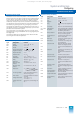
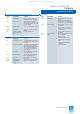
Blocks for analog and digital processing
Type Designation Function
SUM
Adder Y = X1 + X2 - X3 - X4
MUL
Multiplier Y = X1 · X2
DIV
Divider Y = X1/X2
RAD
Square-root extractor Y = or Y = K
LN
Logarithm extractor Y =
KF
· Iog
e
| X |
EXP
Exponential value Y = e
x
ABS Absolute value X = | X |
INT
Integrator Y = K · dt, K = 1/T
DIF
Differentiator Y(s)/X(s) = (T·s)/(1 + (T·s/v))
PT
Delay Y(s)/X(s) = 1/(1 + T·s)
TOZ
Dead time Y(s)/X(s) = e
-s·T
MIN Minimum-value
selector
Y = minimum of X1, X2, X3
MAX
Maximum-value
selector
Y = maximum of X1, X2, X3
TOB
Dead band Y = X-TOBU for X < TOBU
0for TOBU ≤
X
≤
TOBO
X-TOBO for X > TOBO
PLG
Function generator Linear interpolation between 6
pairs of turning points
GW
Limit monitor Limit check between two switch-
ing points
ASL
Analog-value switch Y = X1 for S = “0”
Y = X2 for S = “1”
SPEI
Analog-value mem-
ory
Storage of up to 256 analog val-
ues
X X
X
∫
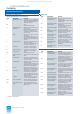
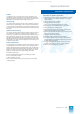
Blocks for binary processing
Type Designation Function
VU
AND A = E1 ∧ E2 ∧ E3
VO
OR A = E1 ∨ E2 ∨ E3
VN
Negation A = E
VM Flag Flag of binary input signals (flip-
flop)
VZ
Time delay Switch-on and switch-off delays
VS + STEP
STEP M block Freely programmable in STEP M
MPX
Multiplexer To supply the STEP commands in
the following VS/KS block
BW
Binary selection Selection of status combination
from up to 3 binary signals
INKU
Incremental con-
verter
Converts analog value into an
open or close pulse
BCE
BCD input Conversion of a BCD signal into
an analog value
BCA
BCD output Conversion of an analog value
into a BCD signal
KA
KAK
Sequence start Marks the start of an ON/OFF
branch of a subgroup control
As KA, but with additional func-
tions
KB
KBK
Sequence Conditions of a control step, for
power plants
As KB, but with additional func-
tions
KS
Sequence step As KB, for process plants
KV
Sequence branch Branch of a sequence into a max-
imum of 6 branches, with process
plants
KE
KEK
Sequence end Last block in a sequence
As KE, but with additional func-
tions
HA
Auxiliary oil auto-
matic unit
Controls electric auxiliary oil
pumps for oil supply to generator
sets
HUP
Horn block Triggers signalling equipment
(optical and audible)
EAR
Individual analog-
value allocation
Allocates analog values from out-
puts in GA blocks
EBR
Single-bit allocation Links individual binary outputs to
GB/GM data blocks
UBR
Universal binary
location
Links 16 binary outputs to GB/
GM data blocks
This catalog is out of date, see note on page 1