s TELEPERM M Introduction System architecture AS 235, AS 235 H and AS 235 K Automation Systems Automation systems I/O modules Catalog PLT 111 · 1999 Input and output devices Bus communication This catalog is no longer available in printed form. However, it can still be used to obtain information and for ordering spare parts. Certain products from this catalog are no longer available. Your Siemens partner will offer appropriate substitutes wherever possible.
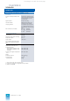
This catalog is out of date, see note on page 1 TELEPERM M Introduction Brief description TELEPERM M process control system The TELEPERM M process control system provides all functions required for process automation. It is highly suitable for the complete automation of continuous and discontinuous (batch) processes.
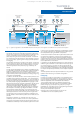
This catalog is out of date, see note on page 1 TELEPERM M Introduction Brief description WinCC/TM-OS operator terminals WinCC/TM-OS operator terminals SIMATIC PCS 7 operator terminals Terminal bus WinCC/TMOS server WinCC/TMOS server PROGRAF AS+ configuring software incl. WinCC/TM-CS 275 incl.
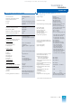
This catalog is out of date, see note on page 1 TELEPERM M Introduction System data General system data General system data 1) Permissible ambient temperature • Analog signals • Modules – Operation – Δt/h – Δt/min – Transport and storage 0 to 70 °C Max. 10 K Max.
This catalog is out of date, see note on page 1 TELEPERM M Introduction System data Technical data of automation systems Central unit Microprogrammed Arithmetic unit processing width 32 bit Process execution levels 5 • Acyclic 2 (alarm and background levels) • Cyclic 2 (125 ms, 1 s) and communication level Memory (EDC) 1-bit correction when reading Interface to central processor 16 bit wide Main memory (RAM) 4000 kbyte Memory for system software (RAM) 1 Mbyte Memory backup time (RAM) T
This catalog is out of date, see note on page 1 TELEPERM M Introduction System data Technical data of automation systems (continued) I/O modules Function modules/calculation modules Autonomous closed-loop and individual control drive modules or user-configured with own microprocessor Signal modules Binary and analog Counter modules Metered pulse module, proportioning counter module Coupling modules For SIMATIC S5/S7 peripheral I/O modules and devices, and for subordinate devices and systems M
This catalog is out of date, see note on page 1 System architecture 2/2 2/4 Performance characteristics Redundancy with AS 235 H 2/5 2/10 Standard function blocks User function blocks Configuring Siemens PLT 111 · 1999 2/1
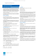
This catalog is out of date, see note on page 1 System architecture Performance characteristics Performance characteristics The AS 235, AS 235 H and AS 235 K systems are programmable automation systems of the TELEPERM M process control system based on function blocks. They have a different design and availability, but the same range of functions. The AS 235 K system is fitted in a wall housing, the AS 235 and AS 235 H systems are fitted in cabinets.
This catalog is out of date, see note on page 1 System architecture Performance characteristics STEP M In addition to the function blocks for binary processing, the AS 235/235 H/235 K systems can use the STEP M control language, without leaving the block configuration, in order to formulate extensive and complex open-loop control tasks. TML language The TML process language can be used in addition to the firmware blocks for special tasks.
This catalog is out of date, see note on page 1 System architecture Redundancy with AS 235 H CS 275 plant bus Central processing unit I Synchronization Comparison, cross-coupling Central processing unit II Redundant I/O bus Comparison, switchover I/O bus Comparison, switchover I/O bus I/O modules I/O modules Redundant path 1-out-of-2 redundancy structure with AS 235 H Redundancy with the AS 235 H automation system Various system characteristics must be considered with regard to the reliability a
This catalog is out of date, see note on page 1 System architecture Configuring Standard function blocks Standard function blocks Blocks for binary processing Dedicated function blocks are present in the automation systems to solve the control tasks. These are the so-called standard function blocks. The AS 235, AS 235 H and AS 235 K systems have the same standard function blocks for data acquisition, closed-loop and open-loop control, calculation and monitoring.
This catalog is out of date, see note on page 1 System architecture Configuring Standard function blocks Blocks for processing with standardized operation and monitoring Type Designation Function R Closed-loop controller PID control, e.g.
This catalog is out of date, see note on page 1 System architecture Configuring Standard function blocks Driver blocks for I/O modules Type Designation Function For modules with Order No.
This catalog is out of date, see note on page 1 System architecture Configuring Standard function blocks Driver blocks for configurable TELEPERM ME I/O modules Type Designation Function For modules with Order No.
This catalog is out of date, see note on page 1 System architecture Configuring Standard function blocks Output blocks for printer and process monitor Test blocks Type Designation Function Type Designation Function GP Group display Design of display hierarchy: area display and group display TANZ Test display MEL Alarm output Output of planned plain text alarms with time (resolution 1 s); also standard blocks, such as M, generate alarms Monitoring of binary and analog variables; selec
This catalog is out of date, see note on page 1 System architecture 2/2 2/4 Performance characteristics Redundancy with AS 235 H 2/5 2/10 Standard function blocks User function blocks Configuring Siemens PLT 111 · 1999 2/1
This catalog is out of date, see note on page 1 System architecture Performance characteristics Performance characteristics The AS 235, AS 235 H and AS 235 K systems are programmable automation systems of the TELEPERM M process control system based on function blocks. They have a different design and availability, but the same range of functions. The AS 235 K system is fitted in a wall housing, the AS 235 and AS 235 H systems are fitted in cabinets.
This catalog is out of date, see note on page 1 System architecture Performance characteristics STEP M In addition to the function blocks for binary processing, the AS 235/235 H/235 K systems can use the STEP M control language, without leaving the block configuration, in order to formulate extensive and complex open-loop control tasks. TML language The TML process language can be used in addition to the firmware blocks for special tasks.
This catalog is out of date, see note on page 1 System architecture Redundancy with AS 235 H CS 275 plant bus Central processing unit I Synchronization Comparison, cross-coupling Central processing unit II Redundant I/O bus Comparison, switchover I/O bus Comparison, switchover I/O bus I/O modules I/O modules Redundant path 1-out-of-2 redundancy structure with AS 235 H Redundancy with the AS 235 H automation system Various system characteristics must be considered with regard to the reliability a
This catalog is out of date, see note on page 1 System architecture Configuring Standard function blocks Standard function blocks Blocks for binary processing Dedicated function blocks are present in the automation systems to solve the control tasks. These are the so-called standard function blocks. The AS 235, AS 235 H and AS 235 K systems have the same standard function blocks for data acquisition, closed-loop and open-loop control, calculation and monitoring.
This catalog is out of date, see note on page 1 System architecture Configuring Standard function blocks Blocks for processing with standardized operation and monitoring Type Designation Function R Closed-loop controller PID control, e.g.
This catalog is out of date, see note on page 1 System architecture Configuring Standard function blocks Driver blocks for I/O modules Type Designation Function For modules with Order No.
This catalog is out of date, see note on page 1 System architecture Configuring Standard function blocks Driver blocks for configurable TELEPERM ME I/O modules Type Designation Function For modules with Order No.
This catalog is out of date, see note on page 1 System architecture Configuring Standard function blocks Output blocks for printer and process monitor Test blocks Type Designation Function Type Designation Function GP Group display Design of display hierarchy: area display and group display TANZ Test display MEL Alarm output Output of planned plain text alarms with time (resolution 1 s); also standard blocks, such as M, generate alarms Monitoring of binary and analog variables; selec
This catalog is out of date, see note on page 1 Automation systems 3/2 General 3/3 3/6 3/7 3/8 3/8 3/8 Basic cabinet Ordering data for basic cabinet Options for basic cabinet Extension cabinet Ordering data for extension cabinet Options for extension cabinet 3/9 3/14 3/15 3/16 3/17 3/17 Basic cabinet Ordering data for basic cabinet Options for basic cabinet Extension cabinet Ordering data for extension cabinet Options for extension cabinet 3/18 3/20 3/20 Basic system Ordering data for AS 235 K Optio
This catalog is out of date, see note on page 1 Automation systems General AS 235 K Automation systems ES 100 K ES 100 K EE4 GE AS 235 EE5 ES 100 K Further ES 100 K systems, max. 4 EE1 EE6 EE2 EE3 ES 100 K b a Distributed configuration: AS 235 K automation system, can be extended by up to eight ES 100 K extension systems Central configuration: AS 235 automation system with basic and extension cabinets, max 6 extension units EE Extension unit GE Basic unit Fig.
This catalog is out of date, see note on page 1 Automation systems AS 235 Basic cabinet AS 235 automation system Communication via CS 275 plant bus The AS 235 automation system is the cabinet version of the range. It can be ordered in the form of two ordering units: basic cabinet and extension cabinet: GE The basic cabinet is the main component of the AS 235 automation system. It contains all components required for the AS 235 system to function. It can therefore also be used on its own, i.e.
This catalog is out of date, see note on page 1 Automation systems AS 235 SV2 SV2 ML2 SV1 ML1 Basic cabinet SSO GE AS 235 BAB/DG CPU RAM 6 AMD 5 N-AS 4 BK1 3 EAB1 2 BK2 1 EAB2 EE4 EE5 EE1 Slots for I/O modules EE6 EE2 EE3 AS 235 basic unit V1 V2 SI AV UI Bus A UI Bus B SVZ DC24V BT AS 235 basic cabinet AS 235 extension cabinet Power distribution subrack AMD AV BAB BK BT CPU DG EAB EE GE Interface module for mini floppy disk unit Connection distributor for 20-m local bu
This catalog is out of date, see note on page 1 Automation systems AS 235 Basic cabinet When ordering the extension units it is possible to select whether the extension unit EE1 is to be delivered on its own, together with EE2, or together with EE2 and EE3.
This catalog is out of date, see note on page 1 Automation systems AS 235 Ordering data for basic cabinet With the standard ordering configuration, an additional connection unit for a single or redundant remote bus can be selected under “Power supply and bus components” in addition to the power supply unit.
This catalog is out of date, see note on page 1 Automation systems AS 235 Options for basic cabinet Ordering data Order No.
This catalog is out of date, see note on page 1 Automation systems AS 235 Extension cabinet Extension cabinet Ordering data Depending on the complexity of the automation task, the capacity of the basic unit can be increased to a maximum of 90 slots for I/O modules by using up to 6 extension units. The extension units EE4 to EE6 are fitted in the extension cabinet and thus connected to the central processing unit via I/O bus 2 (B) and the interface module for I/O bus 2 (B).
This catalog is out of date, see note on page 1 Automation systems AS 235 H Basic cabinet AS 235 H automation system The AS 235 H automation system is the high-availability cabinet version of the AS 235 range. In contrast to the simple cabinet version, the AS 235 H is of redundant design and operates according to the 1-out-of-2 principle.
This catalog is out of date, see note on page 1 Automation systems AS 235 H Basic cabinet Partial system I Partial system II Backup module DC 24 V SV SV EE4 GE AS 235 H EE5 EAVU EE1 EE6 N-AS EAVU BK2 EAB2 BK1 EAB1 AMD CPU RAM BAB/DG SB VKB SB BAB/DG RAM CPU AMD BK2 EAB2 BK1 EAB1 N-AS EE2 EE7 EE3 AS 235 H basic unit SES Automatic circuit-breakers ML ML ML VD VD 1 2 3 1 2 ST1 AS 235 H basic unit V1 V2 ST2 AV UI Bus A UI Bus B AS 235 H extension cabinet BT Power supply subra
This catalog is out of date, see note on page 1 Automation systems AS 235 H Basic cabinet Standard I/O devices The standard I/O devices such as process monitor, process operation keyboard, configuring keyboard, mini floppy disk unit, logging printer and message printer are described in Section 5. The interface modules for operation channel generate the RGB signals for the process monitors.
This catalog is out of date, see note on page 1 Automation systems AS 235 H BE EEn+1 EAVU EEn BA Fig. 3/6 Example of redundancy with I/O modules (1-out-of-2 structure) BE EAVU Basic cabinet BA BA Binary output module BE Binary input module EAVU I/O bus comparator and switchover module EE Extension unit Some of the I/O modules are suitable for producing a redundant process I/O area and for thus implementing an interruption-free automation system.
This catalog is out of date, see note on page 1 Automation systems AS 235 H Basic cabinet The connection unit for a redundant AS 235 H basic unit comprises: • 2 interface modules for 20-m local bus N-AS • Bus converter UI (2 x with redundant remote bus) • Connector board AF “Remote bus” (2 x with redundant remote bus) • For redundant remote bus: connecting cable with 5 plugs for connection of N-AS to bus converters 1 and 2 and connection distributor for 20-m local bus 6DS1 223-8AA 6DS4 400-8AB 6DS9 203-
This catalog is out of date, see note on page 1 Automation systems AS 235 H Ordering data for basic cabinet Ordering data AS 235 automation system, basic cabinet Basic unit • Without basic unit • Basic unit 4 Mbyte, with I/O bus 1, redundant design • Basic unit 4 Mbyte, with I/O bus 1, non-redundant design Standard I/O devices • Without standard I/O devices • Operation channel 1 with process operation and configuring keyboards, for redundant basic unit – Without process monitor – With process monitor
This catalog is out of date, see note on page 1 Automation systems AS 235 H Options for basic cabinet Ordering data Order No.
This catalog is out of date, see note on page 1 Automation systems AS 235 H Extension cabinet Ordering data Order No. Options for AS 235 H basic cabinet (continued) Depending on the complexity of the automation function, the AS 235 H can be increased up to max. 91 slots for I/O modules by using up to 7 extension units.
This catalog is out of date, see note on page 1 Automation systems AS 235 H Ordering data for extension cabinet Ordering data AS 235 H automation system, extension cabinet Extension units • Without extension units For redundant basic units, each with alarm logic module 3 and 2 interface modules for I/O bus 2 • Extension unit EE4 – Wire-wrap system – Maxi-Termi-Point system • EE4 and EE5 – Wire-wrap system – Maxi-Termi-Point system • EE4, EE5 and EE6 – Wire-wrap system – Maxi-Termi-Point system • EE4,
This catalog is out of date, see note on page 1 Automation systems AS 235 K Basic system AS 235 K automation system Communication via CS 275 plant bus The AS 235 K automation system is the compact version of the AS 235 system. Both systems use the same central unit modules, interface modules and I/O modules. They also have the same range of functions. 4(6) I/O modules The AS 235 K system is fully operable on its own without any extensions.
This catalog is out of date, see note on page 1 Automation systems AS 235 K Basic system soles are to be used via which operation and monitoring or configuring are to be carried out independently.
This catalog is out of date, see note on page 1 Automation systems AS 235 K Ordering data for AS 235 K Max. 2 interface modules N-V.24 inserted in one of the I/O slots in the AS 235 K basic system can be integrated via a front connection to the interface module N-AS of the system by means of cable 6DS8 201-8.. . Please contact Siemens in the case of other participants and additions. The cable 6DS8 201-8.. is only provided with a plug at one end.
This catalog is out of date, see note on page 1 Automation systems ES 100 K ES 100 K extension system ES 100 K extension system Up to eight ES 100 K extension systems can be connected in order to supplement the 6 I/O module slots in the AS 235 K system (max. 4 systems per I/O bus). Extension of the AS 235 system by the ES 100 K extension system is also possible. Each ES 100 K system has space for 13 I/O modules.
This catalog is out of date, see note on page 1 Automation systems ES 100 K Ordering data for ES 100 K Ordering data Ventilation roof ES 100 K extension system Order No. 6DS2 103 - Basic system • Extension system AC 230 V • Extension system DC 24 V 1 X X 0 2 X X 0 600 x 360 630 1 U = 44.5 mm ES 100 K options 29 15 Æ 10.2 702 820 760 15 U Housing • Without housing • Sheet-steel housing, degree of protection IP 21, without heat exchanger 40 Fig.
This catalog is out of date, see note on page 1 Automation systems Standard cabinets Standard cabinets and accessories Standard cabinets and accessories The AS 235 and AS 235 H automation systems can be delivered in 400 mm or 600 deep standard cabinets with or without a heat exchanger.
This catalog is out of date, see note on page 1 Automation systems Standard cabinets Ordering data for system cabinet accessories Ordering data Order No. Ordering data System cabinet accessories System cabinet accessories (continued) Cabinet connection element SAE 32/1 with screw attachment SAE 32 S (max. 40 off/cabinet) Process side: screw attachment SAE 32 S Internal: Maxi-Termi-Point 2.4 x 0.
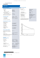
This catalog is out of date, see note on page 1 Automation systems Standard cabinets Permissible thermal loading Permissible thermal loading, configuring guidelines Standard cabinets without forced ventilation Basic and extension units fitted in standard cabinets can be operated without fans if • the cabinet thermal load Ps max permissible depending on the cabinet unit temperature is not exceeded and • a heat loss greater than 150 W does not occur in any extension system.
This catalog is out of date, see note on page 1 Automation systems Standard cabinets Standard cabinets IP 20 without heat exchanger 2,3 The cable bars are included in the standard delivery of the cabinet. The locations for installation of the video relays and the connector boards for remote bus are identified accordingly.
This catalog is out of date, see note on page 1 Automation systems Standard cabinets Standard cabinets IP 54 with heat exchanger 2,3 The cable bars are included in the standard delivery of the cabinet. The locations for installation of the video relays and the connector boards for remote bus are identified accordingly.
This catalog is out of date, see note on page 1 Automation systems Process connection systems Process connection systems Process connection systems Process signal cables, information on cable routing The process signal cables should be screened installation cables for industrial electronics with color-coded conductors twisted in pairs and combined into bundles. Highly suitable are SIMATIC cables with a conductor cross-section of 0,5 mm² (conductor diameter 0.8 mm).
This catalog is out of date, see note on page 1 Automation systems Connection diagrams Standard I/O devices to AS 235 / AS 235 K Connection diagrams for standard I/O devices to AS 235 / AS 235 K Process monitor Process monitor AS 235 basic unit / AS 235 K basic system AC 115 V or AC 230 V R G B 167-8B R G B PBT 116 BK2 Process operation keyboard Configuring keyboard BK1 167-8C 167-8B Process operation keyboard 167-8A DC 24 V from SV1 116 PDR MDR 167-8C 102 AC 115 V or AC 230 V R G B
This catalog is out of date, see note on page 1 Automation systems Connection diagrams Connection of personal computer Process monitor Process monitor AS 235 basic unit / AS 235 K basic system AC 115 V or AC 230 V R G B R G B PBT 116 BK2 Process operation keyboard Configuring keyboard BK1 167-8C Process operation keyboard 167-8A External DC 24 V supply on site 116 PDR MDR 167-8C 102 AC 115 V or AC 230 V R G B 102 Configuring keyboard 167-8A 104 104 Logging printer External DC 24
This catalog is out of date, see note on page 1 Automation systems Connection diagrams Connection of process monitors and parallel monitors Connection of process monitors and parallel monitors Process monitor 1 R G B 116 BK2 BK1 Process monitor *) Via T-pieces Via T-pieces 117 AC 115 V or AC 230 V AS 235 basic unit / AS 235 K basic system AC 115 V or AC 230 V a b In the case of process monitors connected in parallel, the total of all looped cable lengths (a + b + c + ...
This catalog is out of date, see note on page 1 Automation systems Connection diagrams Standard I/O devices to AS 235 H Connection diagrams for standard I/O devices to AS 235 H Process monitor Process monitor Video relay 2 Video relay 1 116 116 T1 BK2 BK1 T2 BK2 BK1 R G B PBT AC 115 V or AC 230 V T Partial system BK Interface module for operation channel AC 115 V or AC 230 V PDR MDR AS 235 H basic unit TV Keyboard distributor DV Printer distributor TV DV DV 167-8B Connections Connections f
This catalog is out of date, see note on page 1 Automation systems Connection diagrams Standard I/O devices to AS 235 H Process monitor Process monitor Video relay 2 Video relay 1 116 116 T1 BK2 BK1 T2 BK2 BK1 R G B PBT AC 115 V or AC 230 V T Partial system BK Interface module for operation channel AC 115 V or AC 230 V PDR MDR AS 235 H basic unit TV Keyboard distributor DV Printer distributor TV DV DV Connections Connections for operation for operation channel 2 channel 1 DV DV TV 167-8C
This catalog is out of date, see note on page 1 Automation systems Connection diagrams Summary of connecting cables Item Connecting cable From Plug 1 Plug 2 Cable Max. cable length Order No. Page To 102 Configuring keyboard Signal distribution unit 6DS9 913-8DA 1) or process operation keyboard 15-contact (Cannon, sockets) 15-contact (Cannon, pins) L-YCY 12 x 2 x 0.22 10 m 2) 6DS8 102-8..
This catalog is out of date, see note on page 1 I/O modules 4/2 Summary 4/5 4/5 Closed-loop control modules Calculation modules 4/6 4/7 Analog input and output modules Binary input and output modules 4/8 4/8 Proportioning counter module Metering pulse input module 4/8 4/8 4/9 Configuring aids Coding, inserting and labelling Modules which can be used on the I/O bus Function modules Signal modules Proportioning and counter modules Configuring Siemens PLT 111 · 1999 4/1
This catalog is out of date, see note on page 1 I/O modules Summary This section lists the available input and output modules of the TELEPERM M range. A detailed description of all modules (including those which are no longer available) with photos, functional diagrams and complete technical data can be found in Internet at: http://www.ad.siemens.de/teleperm in the section "Process I/Os - TELEPERM M". Summary The I/O modules constitute the interface of the automation system to the process.
This catalog is out of date, see note on page 1 I/O modules Summary I/O modules Summary of properties General technical data Power supply L+ Rated voltage DC 24 V Permissible range 20 to 33 V including superimposed ripple Permissible superimposed ripple Upp 15 % of mean value of DC voltage • Modules can be replaced during operation Limiting range of use 35 V, max. 500 ms 45 V, max. 10 ms • Comprehensive self-test routines on the modules Voltage dip 0 V, max. 5 ms; recovery time min.
This catalog is out of date, see note on page 1 I/O modules Summary I/O modules from other systems Selection criteria for I/O modules I/O modules from other systems can be operated on the I/O bus of an AS 235 automation system via existing parallel and serial links (see Section 7). There are various criteria for selecting the most suitable I/O modules for a particular application; these criteria must be evaluated depending on the respective application.
This catalog is out of date, see note on page 1 I/O modules Function modules Closed-loop control modules Function modules Function modules have their own functions which are independent of the central unit. They possess backup modes which permit operation independent of the central unit. Some of the function modules are configurable. The firmware of these configurable modules contains an interpreter which processes a user configuration made up of defined blocks.
This catalog is out of date, see note on page 1 I/O modules Signal modules Analog input and output modules Signal modules Analog input/output modules and binary input/output modules are available as signal modules.
This catalog is out of date, see note on page 1 I/O modules Signal modules Binary input and output modules Binary input and output modules The following modules are available: • Binary input module with 48 inputs, non-floating, with interrupt control, 6DS1 601-8BA To input 48 binary signals DC 24 V (non-floating) to the central unit of an automation system, optionally with interrupt control.
This catalog is out of date, see note on page 1 I/O modules Proportioning and counter modules Proportioning counter module, metering pulse input module Counter modules Configuring Two counter modules are available: • Proportioning counter module with 2 or 4 channels, 6DS1 613-8BB For counting and largely autonomous processing of metering pulses, independent of the superimposed automation system.
This catalog is out of date, see note on page 1 I/O modules Configuring Modules which can be used on the I/O bus Modules which can be used on the I/O bus The following table does not refer to the availability of modules but to their approval for use in AS 235 systems. Designation Order No.
This catalog is out of date, see note on page 1 I/O modules Configuring Modules which can be used on the I/O bus Explanations for the column "Remarks" Designation Order No. of module Release 6DS1 715-8BB ≥2 SW:03 Binary calculation module 6DS1 717-8AA ≥8 SW:08 Binary/analog calculation module (max.
This catalog is out of date, see note on page 1 Input and output devices Operation unit PBT 65 process operation keyboard The 4 authorization stages have the following meaning: • Stage 1: keyboard "OFF", no operation possible • Stage 2: process operation keyboard "ON" • Stage 3: configuring keyboard "ON" • Stage 4: configuring keyboard and process operation keyboard "ON". A 4-digit password which can be individually modified is assigned to each authorization key.
This catalog is out of date, see note on page 1 Input and output devices Configuring unit Configuring keyboard Technical data Interface 20-mA current loop interface, floating (active) Transmission rate 1200 bits/s Parity and stop bits Active 1200 bits/s, even parity, 2 stop bits Power supply DC 24 V (20 to 33 V); 0.2 A Permissible ambient temperature – Operation – Storage +5 to +40 °C -40 to +70 °C Permissible relative humidity Max.
This catalog is out of date, see note on page 1 Input and output devices Configuring unit Mini floppy disk unit Technical data Data medium Floppy disk; 5,25 inch Data capacity 1.2 Mbytes Data transfer rate 300 kbits/s Power supply DC 24 V (20 to 33 V); approx. 0.52 A; approx. 0,74 A during motor startup for 400 ms Permissible ambient temperature – Operation – Storage +10 to +40 °C -20 to +65 °C Permissible relative humidity 20 to 80 %, no condensation Vibration resistance – Operation Fig.
This catalog is out of date, see note on page 1 Bus communication 6/2 6/2 6/5 6/6 Application Design Bus configurations Connecting cables Siemens PLT 111 · 1999 6/1
This catalog is out of date, see note on page 1 Bus communication Application Bus communication AS 235, AS 235 H and AS 235 K can only be operated on the CS 275 plant bus, but can also communicate with automation systems and operator systems on the PROFIBUS-TM plant bus via a CS-L2 bridge. UI This section only describes bus communication with the CS 275 plant bus. A description of bus communication via the PROFIBUS-TM plant bus can be found in Catalog PLT 112.
This catalog is out of date, see note on page 1 Bus communication Design If e.g. automation systems are to be connected together via a local bus, the following are required for n participants: • n interface modules for 20-m local bus (cf. table on page 6/5) • n-1 cables 6DS8 201-8.. • 1 front plug 6DS9 200-8AA. 2 interface modules N-AS are required for the AS 235 H system. These are handled as one participant, i.e. the same bus address is set on both interface modules.
This catalog is out of date, see note on page 1 Bus communication Design Connection distributor AV or N-AS N-AS 6DS9 201-8CA or 6DS8 204-8.. (without AV) N-AS 6DS8 201-8.. AF Bus converter Ul A bus converter is required to connect individual participants or a local bus with several participants to a remote bus. It performs continuous signal conversion between the local bus and the remote bus or vice versa without intermediate storage. The coupling is inductive and non-reactive.
This catalog is out of date, see note on page 1 Bus communication Bus configurations Bus configurations, examples 20-m local bus N 1 N 2 .... max. N 9 20-m local bus / 4-km remote bus N 1 N 2 .... N max. 8 Application Other conditions Connecting cables Small plants Max. 9 participants possible Max. 20 m bus cable Standard design redundant Can only be used in instrumentation rooms. The guidelines for earthing and screening must be observed for the participants on the local bus.
This catalog is out of date, see note on page 1 Bus communication Connecting cables Connecting cables for 20-m local bus Connecting cables for remote bus To connect the interface modules for 20-m local bus to one another and to the bus converter UI. A front plug is required for the last participant on the local bus when using the cable 6DS8 201-8.. . Ordering data Ordering data Order No.
This catalog is out of date, see note on page 1 Coupling with other systems 7/2 Summary 7/3 Parallel coupling with S5-115U I/O modules Parallel coupling with S5-135U / 155U I/O modules Interface module for S5 expansion units SIMATIC S5 expansion units 7/5 7/7 SIMATIC S5/S7 central controllers 7/8 7/9 Serial coupling with SIMATIC S5/S7 central controllers Interface module for SIMATIC S5/S7 central controllers SIMATIC S5 I/Os ET 100U 7/10 7/12 Serial coupling of SIMATIC S5 I/Os Interface module for
This catalog is out of date, see note on page 1 Coupling with other systems Summary Coupling with other systems Interface modules for coupling with other systems, summary Interface module Type of coupling Interface Procedure Electrical isolation Coupling partner 6DS1 321-8AA Parallel, bus connection RS 422 I/O bus interface No SIMATIC S5 expansion units 6DS1 327-8AA Serial, bus connection RS 485 (ET 100) Yes SIMATIC S5 expansion units, ET 100U 6DS1 333-8AB Serial, point-topoint connect
This catalog is out of date, see note on page 1 Coupling with other systems SIMATIC S5 expansion units Parallel coupling with S5-115U I/O modules AS 235, AS 235 H, AS 235 K, ES 100 K .. .. . ER 701-1 ER 701-2 ER 701-1 ER 701-2 I/O bus Channel 1 Connecting cable 721-0 Interface module 6DS1 321-8AA Up to 6 interface modules 6DS1321-8AA with a total of 12 usable channels can be operated per AS 235 automation system. .. .. . Max. 2.
This catalog is out of date, see note on page 1 Coupling with other systems SIMATIC S5 expansion units Parallel coupling with S5-115U I/O modules SIMATIC S5-115U I/O modules appropriate for coupling Module Electrical isolation Number of inputs/outputs Order No.
This catalog is out of date, see note on page 1 Coupling with other systems SIMATIC S5 expansion units Parallel coupling with S5-135U/155U I/O modules AS 235, AS 235 H, AS 235 K, ES 100 K CC-AS IM 312-3 CC/EU-AS 310 I/O bus EU 183U Channel 1 Connecting cable 721-0 CC-AS IM 300-3 EU 184U EU 187U CC-AS IM 312-5 CC-AS IM 312-5 CC/EU-AS 310 EU 183U CC-AS IM 300-5 Terminator All connecting cables 721-0 Channel 2 Interface module 6DS1 321-8AA Central coupling EU 183U EU 184U EU 187U CC-AS IM 31
This catalog is out of date, see note on page 1 Coupling with other systems SIMATIC S5 expansion units Parallel coupling with S5-135U/155U I/O modules SIMATIC S5-135U/155U I/O modules appropriate for coupling Module Electrical isolation Number of inputs/outputs Order No.
This catalog is out of date, see note on page 1 Coupling with other systems SIMATIC S5 expansion units Interface module for SIMATIC S5 expansion units Interface module for SIMATIC S5 expansion units The interface module 6DS1 321-8AA is a compact subassembly, double height (2 standard slots).
This catalog is out of date, see note on page 1 Coupling with other systems SIMATIC S5/S7 central controllers Serial coupling with SIMATIC S5/S7 central controllers SIMATIC central controllers S5-115U/-135U/-155U AS 235, AS 235 H, AS 235 K, ES 100 K I/O bus CP 524 / CP 544 .. .. Channel 1 Channel 2 .. .. Interface module 6DS1 333-8AB SIMATIC automation systems S7-400 / S7-300 CP 441-2 CP 341 max. 1000 m Fig.
This catalog is out of date, see note on page 1 Coupling with other systems SIMATIC S5/S7 central controllers Interface module for SIMATIC S5/S7 central controllers Interface module for SIMATIC S5/S7 central controllers The interface module for SIMATIC S5/S7 central controllers, 6DS1 333-8AB, is a double-height compact subassembly. The front panel width is 30.48 mm (2 standard slots).
This catalog is out of date, see note on page 1 Coupling with other systems SIMATIC S5 I/Os / ET 100U Serial coupling with SIMATIC S5 I/Os AS 235, AS 235 H, AS 235 K, ES 100 K IM 318-3 IM 318-8 I/O bus Terminating resistor ET 100U IM 318-3 Interface module 6DS1 327-8AA EU 183U EU 185U EU 186U ER 701-2 / ER 701-3 IM 318-3 Further connections EU 183U EU 185U EU 186U EU 183U EU 185U EU 186U IM 318-3 max. 3000 m Fig.
This catalog is out of date, see note on page 1 Coupling with other systems SIMATIC S5 I/Os / ET 100U Serial coupling with SIMATIC S5 I/Os ET 100U I/O modules appropriate for coupling Module Electrical isolation Number of inputs/outputs Order No.
This catalog is out of date, see note on page 1 Coupling with other systems SIMATIC S5 I/Os / ET 100U Interface module for ET 100U Interface module for ET 100U The interface module for ET 100U, 6DS1 327-8AA, is a doubleheight compact subassembly. The front panel width is 30.48 mm (2 standard slots). The module has 2 base plugs for the I/O bus interface and the power supply, as well as a front plug (4-contact male connector) with screw terminals for lines 1 and 2.
This catalog is out of date, see note on page 1 Appendix Ordering information Ordering information Appendix Ordering of options Individual components/options and complete systems When ordering options, a differentiation must be made between "Options with assembly" and "Options without assembly". When ordering, a differentiation must be made between individual components/options (e.g. I/O modules, printers) and complete systems (AS 235 standard configurations defined by ordering units).