
Installation Instructions


Siemens Industry, Inc.
Smart Infrastructure
P/N 315-099458-1016
1231234567 8
910111213141516
17 18 19 20 21 22 23 24
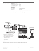
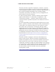
ONE SLOT OF CC-5 #1 WITH HUB-4
INSTALLED
AAAABB BB
++
--++
--
AABB
++
--
PSC-12
TB4
-
TB1
TB2
LLM-1
12 34
12 34
AABB
++
--
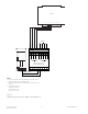
MODEM OR
OR RS-485
INTERFACE
Port #3
MODEM OR
OR RS-485
INTERFACE
Port #4
3.
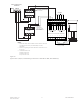
Power limited to NFPA 72 per NEC 760
Shield
MODEM
JP1
JP3
JP2
1.
FSK @ 19.2kbps
Transmit level: 10Dbm
Receive level: 43 Dbm
MODEM OR
OR RS-485
INTERFACE
Port #2
4.
Refer to NIM-1M instructions, P/N 315-099105
configuration settings and specific wiring guidelines
NIM-1M Module
Board
* The LLM-1 inserts
10 ohms between
TB1 and TB2
terminals 2 and 3
(20 ohms total).
*
5.
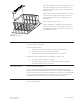
Install the LLM-1 in the MXL enclosure.
2.
Modem Ratings
14-18 AWG 10 miles Max.
20 AWG 6 miles Max.
22 AWG 4 miles Max.
0.8 uf max line to line
14-22 AWG unshielded twisted pair
x
x
x
The interface type
Modem or RS-485)
must match on each
-2 card. If only
one interface is used
on a COM-2 card, it
must be placed on
#1 or Port #3
Chassis
Ground
6.
Positive or negative ground fault detected <5K ohm
s
on CC-5 1-16
NCC-WAN
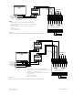
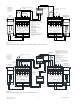
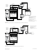
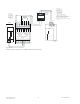
Figure 18
Style 4 Wiring to NIM-1M (with Modem Block) (NCC WAN only)