
Installation Instructions


Siemens Industry, Inc.
Smart Infrastructure
P/N 315-099458-1011
1
2
3
4
1
2
3
4
1
2
3
4
1
2
3
4
1
2
3
4
TB1
TB1
TB2
TB2
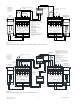
LLM-1
LLM-1
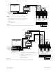
MOM-4
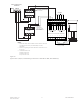
TYPICAL CLASS A (STYLE 7)
CONNECTION
*
USE 2-WIRE
COPPER CABLE,
105 C, 300V, 18 AWG,
SOLID OR STRANDED,
MAX 7 STRANDS.
TWO 2-WIRE 18 AWG CABLE MIN
600 OHM MAX LINE RESISTANCE
TOTAL PER PAIR
*
12345678
910111213141516
+
+
-
-
+
+
--
+
+
--
+
+
--
AA
A
BB
B
BB
B
AA
A
17 18 19 20 21 22 23 24
MODEM 3
MODEM 2
MODEM 4
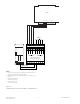
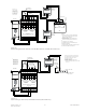
ONE SLOT OF CC-5 WITH HUB-4 INSTALLED
GND FAULT
24V 12A FAIL
24V 4A FAIL
MODULE FAIL
HNET FAIL
CAN FAIL
RESET
POWER
PSC-12
+
_
NON- POWER
LIMITED OUTPUT
(24VDC @ 12A Max.)
(CMI-300)
+
_
BATTERY
TB4
OFF
O
—
ON
TB2
P9
P12
ONES
TENS
HUNDREDS
HNET
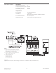
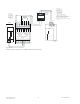
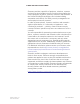
Figure 10
Typical Class A (Style 7) HUB-4 Wiring Connection to CMI-300 on MXL (NCC WAN only)
NOTES
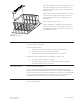
1. Mount the LLM-1 within the MXL enclosure. Refer to the LLM-
1 Installation Instructions, P/N 315-093530, for further
information.
2. Positive or negative ground fault detected at <25K ohms on CC-
5 pins 1-16.
3. 14-18 AWG 8 miles max.
20 AWG 5 miles max.
22 AWG 3 miles max.
0.6 μF max line to line.