
Instruction manual


Camera Parts
& Connections
11
Siemens Building Technologies
Fire Safety & Security Products 03. 2005
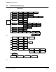
8. External control terminal: (From right to left)
Pin Pin Definition Description
1 Data +
2 Data –
RS485 signal
3 Alarm IN
4 GND
If the alarm IN & GND are shorted, the alarm function will be active.
(Please set ALARM FUNC to ON in OSD menu.)
5 Alarm OUT
6 COM
Alarm output circuit.
7 B/W
8 C/L
9 GND
If D/N MODE set in manual mode, this function will be enabled. If
B/W & GND are shorted, the video signal is monochrome. If C/L &
GND are shorted, the video signal is color.
9. Y/C terminal ⑨
10. Video/ DC lens selection ⑩
11. OSD control button ⑪
12. PC connection port: For factory testing only; the user is not recommended to
use this function. ⑫
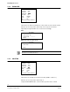
6.2 Connector Pin Definitions
IRIS pin assignment
Video Lens DC Lens
1. +12V 1. Damp-
2. NC 2. Damp+
3. VIDEO 3. Drive +
4. GND 4. Drive-
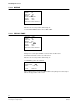
Y/ C terminal
1 GND
2 GND
3 Y (luminance, 1 Vpp, 75 Ω)
4 C (chrominance, 0.3 Vpp (burst), 75 Ω)