
User Manual


5/6
Siemens Building Technologies COM1 communication cards CM2N8311E
Landis & Staefa Division 05.10.2000
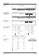
Internal diagrams
PVC1.1S
X5
PVX1.1C
PHONE SDLC-Ring
PHONE
SDLC-Ring
1A 3A2B 4B 11A 13A12B 14B5 6 15 167 17
8311G01
PHONE SDLC-Ring
PHONE
SDLC-Ring
PVC1.1ST / BPS1.C1/1ST
X5
PVX1.1C
X2 X3
TTY1/V.24 TTY2/V.24
1A 3A2B 4B 11A 13A12B 14B5 6 15 167
8311G02
17
PVC1.1T
X5
X2 X3
TTY1/V.24 TTY2/V.24
8311G03
Terminal Signal Designation Terminal Signal Designation
1 A IN A SDLC ring 11 A IN A SDLC ring
2 B IN B SDLC ring 12 B IN B SDLC ring
3 A OUT A SDLC ring 13 A OUT A SDLC ring
4 B OUT B SDLC ring 14 B OUT B SDLC ring
5 IN A PHONE (field telephone) 15 OUT A PHONE (field tele-
phone)
6 IN B PHONE 16 OUT B PHONE
7
Cable screen 17 Cable screen
X2 Primary interface TTY1 Modem connection
X3 Secondary interface TTY2, Printer connection
X5 Internal plug connection to basic unit PRV2... / BPS1.ECU
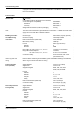
Signals
as per CCITT
Modem
TTY1
Printer
TTY2
Pin assignment
1
13
14 25
8311G04
TXD Output Output 2
RXD Input Input 3
RTS Output Output 4
CTS Input Input 5
DSR Input – 6
SGND Ground Ground 7
DCD Input – 8
DTR Output – 20
Shield Shield Housing
Card for BLN bus
(SDLC)
.
.
Card for BLN bus
(SDLC) and V.24 on
TTY1 and TTY2
.
.
.
.
.
.
.
.
Card for V.24 on
TTY1 and TTY2
PVX1.1C connections,
terminal block III
Plugs
.
.
X2 and X3 pin as-
signment