
Specifications


Setting Airflow Setpoints
14
Siemens Industry, Inc.
140-0893 Start-up
Draft
1/12/2010
Setting Airflow Setpoints
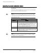
NOTE:
Maximum flow(s) must be set ≥ minimum flow(s).
1. Set CLG FLOW MIN to the desired minimum cooling airflow setpoint.
2. Set CLG FLOW MAX to the desired maximum cooling airflow setpoint.
Application 2861 through 2867
3. Set HTG FLOW MIN to the desired minimum heating airflow setpoint.
4. Set HTG FLOW MAX to the desired maximum heating airflow setpoint.
5. Set FLOW START to the heating loopout percentage that the flow will start to
modulate in the heating mode. (that is, at HTG FLOW MIN).
6. Set FLOW END to the heating loop out percentage that the flow will end
modulation (that is, at HTG FLOW MAX).
In addition to the flow setpoints in the heating mode (HTG FLOW MIN and HTG
FLOW MAX), the parameters FLOW START (default is 0) and FLOW END (default
is 100) will determine what portion of the HTG LOOPOUT the flow will modulate
the heating mode. CAUTION: If FLOW START equals FLOW END, the flow will not
modulate even if HTG FLOW MAX is greater than HTG FLOW MIN.
NOTE:
For Applications 2862, 2863, 2864 and 2866, HTG FLOW MAX should be less
than CLG FLOW MAX. Otherwise, cold supply air may cool rather than heat the
space in heating mode. A typical setting for HTG FLOW MAX is 50% or less of
CLG FLOW MAX.
CAUTION
For electric heating coils in the air terminal unit without a terminal fan, do not set
HTG FLOW MIN to 0.
Equipment damage may occur if insufficient air flow is present with electric heat
ON.