
Network Router User Manual

Wiring the S7-400
4-36
Automation System S7-400 Hardware and Installation
A5E00850741-01
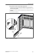
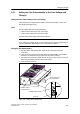
7. Open the cover of the first receive IM (interface module in the ER).
8. Plug the free end of the c onnecting cable into the upper male connector
(receive interface) of the receive IM and screw the connector on.
9. Connect the remaining receive IMs by connecting one send interface (lower
female connector X2) to one receive interface (upper male connector X1) in
each case.
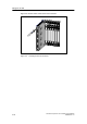
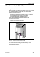
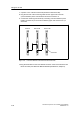
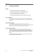
Send IM Receive IM Receive IM
Terminator
Figure 4-23 Connection Between a Send IM and Two Receive IMs
10.Plug the terminator into the lower female connector of the receive IM in the last
ER of the chain (see Reference Manual Module Specifications, Chapter 6).