
Network Router User Manual

Wiring the S7-400
4-16
Automation System S7-400 Hardware and Installation
A5E00850741-01
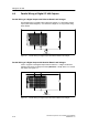
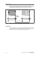
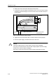
Figure 4-8 shows the methods described here. If the permissible potential
difference between grounding points is exceeded, you must install an equipotential
bonding conductor (copper conductor with a cross-section of ≥ 16 mm
2
).
CR
ER
Send IM
Receive IM
Shield/
protective
ground bar
< 7V
Figure 4-8 Shielding and Grounding the Connecting Cable for a Remote Connection
Special Cases
For remote connections, you must use precut/preassembled c onnecting cables of
fixed length. When the connecting cables are laid, therefore, there may be excess
lengths. These must be coiled w ith a bifilar winding and deposited.