
Network Router User Manual

Wiring the S7-400
4-11
Automation System S7-400 Hardware and Installation
A5E00850741-01
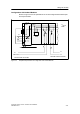
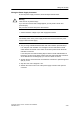
Configuration with Isolated Modules
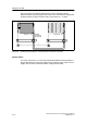
Shown in Figure 4-4 are the potentials of an S7-400 configured with isolated input
and output modules.
PS CPU
L1
N
L+
L1
N
DI DO
PE
Rack
U
internal
Data
M
external
230 VAC load current PS
Ground bus in cabinet
24 VDC load current PS
Figure 4-4 Simplified Representation of Configuration with Isolated Modules