
Network Router User Manual

Assembling and Installing Systems
A-25
Automation System S7-400 Hardware and Installation
A5E00850741-01
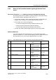
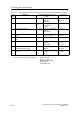
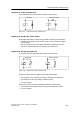
A.9.3 Rules for the Transitions between Lightning Protection
Zones 1 <-> 2 and Greater
Rules for Transitions 1 <-> 2 and Above (Local Equipotential Bonding)
for all lightning protection zone transitions 1 <-> 2 and greater:
• Set up local equipotential bonding at each subsequent lightning protection zone
transition.
• Include all cables (also metal pipelines, for example) in the local equipotential
bonding at all s ubsequent lightning protection zone transitions.
• Include all metal installations located within the lightning protection zone in the
local equipotential bonding (for example, metal part within lightning protection
zone2attransition1<->2
).
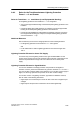
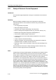
Additional Measures
We recommend you ensure low-voltage protection for the following elements
• for all lightning protection zone transitions 1
<-> 2 and greater
and
• for all cables that run within a lightning protection zone and are longer than
100 m.
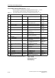
Lightning Protection Element for the 24 VDC Supply
You s hould only use the lightning conductor KT, type 24 VAD SIMATIC for the
24 VDC power supply of the S7-400. All other surge protection components do not
meet the required tolerance r ange of 20.4 V to 28.8 V of the S7-400’s power
supply.
Lightning Protection Element for Signal Modules
You c an use standard overvoltage protection components for the digital I/O
modules. However, please note that these only permit a maximum of 1.15 x V
Nom
=
27.6 V for 24 VDC nominal voltage. If the tolerance of your 24 VDC power supply is
higher, use the surge protection components for 30 VDC nominal voltage.
You c an also use the VT lightning conductor, Type AD 24 V SIMATIC. However,
this can result in the following restrictions:
• Digital inputs: An increased input current can flow in the case of negative input
voltages.
• Digital outputs: Dropout time of contactors can increase significantly.