
Network Router User Manual


Commissioning
6-19
Automation System S7-400 Hardware and Installation
A5E00850741-01
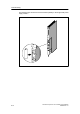
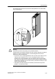
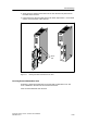
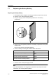
3. Slowly push the interface submodule into the slot until the front plate rests on
theframeofthecardslot.
4. Important! Secure the front plate with the two fitted, captive M2.5 x 10 slot-head
screws on the left frame of the card slot.
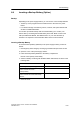
Guide
rails
Figure 6-4 Inserting Interface Submodules in the CPU
Covering Unused Submodule Slots
On delivery, all the submodule slots are secured with a submodule cover. The
cover is attached to the frame of the card slot with screws.
Leave unused submodule slots secured.