
User Manual


9 / 12
Siemens VAV modular controller ASV181.1E/3 CE1N3545en
Building Technologies 2019-03-21
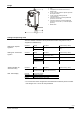
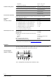
Terminal label
Color code
Terminal code
Description
1
red (RD)
G
System potential AC 24 V
2
black (BK)
G0
System neutral AC 24 V
6
violet (VT)
Y1
Positioning signal "Actuator’s direction of rotation"
(G0 switched) dependent on the setting of direction
7
orange (OG)
Y2
Positioning signal "Actuator’s direction of rotation"
(G0 switched) dependent on the setting of direction
8
grey (GY)
YC
1)
Air volume flow reference signal DC 0/2...10 V
(setpoint) or communication signal
9
pink (PK)
U
Air volume flow measuring signal DC 0/2 ... 10 V
(actual value)
1) To ensure the functions at YC, only one cable may be connected at the time, either the cable for the
air volume flow reference signal DC 0/2...10 V (setpoint) or the cable for the communication signal.
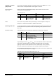
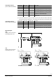
Terminal label
Color code
Terminal code
Description
1
red (RD)
G
System potential AC 24 V
2
black (BK)
G0
System neutral AC 24 V
6
violet (VT)
Y11
Positioning signal "Actuator’s direction of rotation"
(G0 switched) dependent on the setting of direction
7
orange
(OG)
Y22
Positioning signal "Actuator’s direction of rotation"
(G0 switched) dependent on the setting of direction
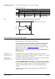
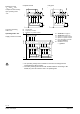
V
V
.const
min
=
V
V
.const
max
=
Connection cable 1
(color coded and labeled)
Connection cable 2
(color coded and labeled)
Wiring diagram
VAV
Supply / extract air control
in operating mode “con”
CAV
Supply / extract air control
in operating mode “con”