
User Manual


7 / 12
Siemens VAV modular controller ASV181.1E/3 CE1N3545en
Building Technologies 2019-03-21
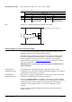
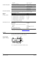
With master/slave control, the DC 0/2…10 V output signal of the controller is fed
into the supply air volume controller (master controller) as the reference variable.
The extract air volume controller (slave controller) receives the master controller’s
actual value signal of the air volume flow as the reference variable (setpoint).
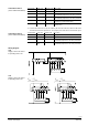
Minimum and maximum limitation of air volume flow
The limitation to
min
V
or
max
V
is made on the relevant controller. This means that
the OEM does not set these limit values on the VAV modular controllers. The
factory settings made by Siemens are 0 % and 100 % and will not be changed.
Here, a differentiation is to be made between two cases, which must be considered
when ordering the air volume controller with the OEM:
• The OEM sets the limit values (
min
V
and
max
V
) on the VAV modular controllers
• The limit values (
min
V
and
max
V
) are set on the assigned room temperature
controller, provided the controller used offers this facility
Disposal
The device is considered electrical and electronic equipment for disposal
in terms of the applicable European Directive and may not be disposed of
as domestic garbage.
• Dispose of the device through channels provided for this purpose.
• Comply with all local and currently applicable laws and regulations.
Technical Data
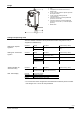
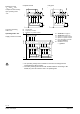
Power supply AC 24 V
Operating voltage / frequency
AC 24 V ±20 % / 50/60 Hz
(SELV/PELV)
G (core 1, red) and
Power consumption
1 VA / 0.5 W
G0 (core 2, black)
Signal inputs
Air volume flow reference or
Input voltage
DC 0/2…10 V
communication signal YC (core 8)
Max. perm input voltage
DC 35 V
Reference signals Y1 (core 6)
Contact sensing
and Y2 (core 7)
Contact sensing
DC 30 V contact voltage
Contact closed
DC 0 V, 8 mA contact current
Signal outputs
Air volume flow measuring signal
Output voltage
DC 0/2…10 V limited to DC 12 V
U (core 9)
Max. output current
DC 1 mA
Time constant (actual value U)
0.05…5 s
Resolution 0.01 s / factory setting 1 s
Configuration and maintenance
interface
Series A-D
6-pin, grid 2.54 mm
As of Series E
7-pin, grid 2.00 mm
Connection cable 1
Cable length
0.9 m
Number of cores
6
Core diameter
6 x 0.75 mm
2
Connection cable 2
Cable length
0.3 m
Number of cores
4
Core diameter
4 x 0.34 mm
2
Degree of protection and
safety class
Degree of protection acc. to EN 60529 (cf. mounting
instruction)
IP40
Safety class acc. to EN 60730
III
Environmental conditions
Operation / transport
IEC 721-3-3 / IEC 721-3-2
Operating mode “3P”
Operating mode “con””