
User Manual


Engineering notes
Depending on the application, it may be necessary to observe additional Installation
Instructions and fit appropriate safety devices (e.g. pressurestats, full motor protection,
etc.).
Warning
In order not to damage the seal inside the valve insert, the plant must be vented on the
low-pressure side after the pressure test has been made (valve port AB), or the valve
must be fully open during the pressure test and during venting (power supply
connected and positioning signal at maximum or forced opening by G → ZC).
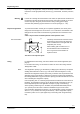
Expansion application
To prevent the formation of flash gas on expansion applications, the velocity of the
refrigerant in the fluid pipe must not exceed 1 m/s. To assure this, the diameter of the
fluid pipe must under certain circumstances be greater than the nominal size of the
valve.
A filter / dryer must be mounted upstream of the expansion valve.
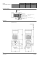
00460
min. 20 x DN
min. 5 cm
MVF661...N
Laboratory measurements reveal that control
performance improves when the refrigerant
valve is installed so that it is higher than the
evaporator (min. 50 mm).
Allow a settling path of at least 0.5 m or
20 x DN between valve and distributor.
This is a general recommendation for
expansion valves.
Recommendation
The valve is not explosion-proof.
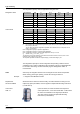
Sizing
For straightforward valve sizing, refer to the tables for the relevant application (from
page 9).
For accurate valve sizing, we recommend to make use of the valve sizing software
"Refrigeration VASP“.
The refrigeration capacity Q
0
is calculated by multiplying the mass flow by the specific
enthalpy differential found in the h, log p-chart for the relevant refrigerant. To help
determine the refrigeration capacity more easily, a selection chart is provided for each
application (page 9 and following). With direct or indirect hot-gas bypass applications,
the enthalpy differential of Q
c
(the condenser capacity) must also be taken into account
when calculating the refrigeration capacity.
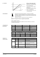
Notes
If the evaporating and / or condensing temperatures are between the values shown in
the tables, the refrigeration capacity can be determined with reasonable accuracy by
linear interpolation (refer to the application examples on page 9 and following).
At the operating conditions given in the tables, the permissible differential pressure
∆p
max
(25 bar) across the valve is within the admissible range for these valves.
If the evaporating temperature is raised by 1 K, the refrigeration capacity increases by
about 3 %. If, by contrast, subcooling is increased by 1 K, the refrigeration capacity
increases by about 1 to 2 % (this applies only to subcooling down to approximately
8 K).
5/16
Building Technologies Refrigerant Valves PN 40 CE2N4716en
HVAC Products 08.06.2005