
User Manual


4716D02en
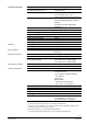
63 %
100 %
0 %
0 % 100 %
Hmax
63 % k
vs
100 % k
vs
(switch 4 = on)
(switch 4 = off)
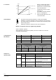
Y-input
Stroke
When k
vs
reduction (DIP switch 4
in position on) the stroke will be
limited to 63 % mechanical stroke.
63 % of full stroke then
corresponds to an input / output
signal of 10 V.
If, in addition, the stroke is limited
to 80 %, for example, the
minimum stroke will be 0.63 x 0.8
= 0.50 of full stroke.
k
vs
reduction
01124
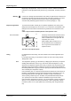
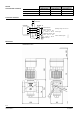
The printed circuit board of the MVF661…N has a slot to facilitate
calibration. To make the calibration, insert a screwdriver in the slot so that
the contacts inside are connected. As a result, the valve will be fully closed
and then fully opened.
Calibration matches the electronics to the valve’s mechanism.
Autocalibration
MVF661…N refrigerant valves are supplied fully calibrated.
When is calibration required?
After replacement of the electronics (ASR61), when the red LED is lit, or when the
valve (valve seat) is leaking.
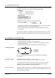
Switch Value off (factory setting) on
1 Positioning signal Y [V] [mA]
2 Positioning range Y and U 0…10 V
0…20 mA
2…10 V
4…20 mA
3 Position feedback U [V] [mA]
4 Flow k
vs
100 % k
vs
63 % k
vs
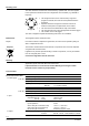
Configuration of
DIP switches
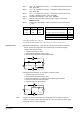
Function of connection terminal
Y (positioning signal) U (position feedback)
Switch 2 Switch 1 Switch 3
off on off on
off 0...10 V 0...20 mA 0...10 V 0...20 mA
on 2...10 V 4...20 mA 2...10 V 4...20 mA
LED State Function Action
LED green Steady on
•
Operation Automatic mode; everything ok
Flashing
•
Calibration in progress
Wait until calibration is terminated
(LED stops flashing)
LED red Steady on
•
Calibration error
•
Internal error
Start stroke calibration again
(short-circuit contacts via slot in PCB)
Replace electronics
Flashing
•
Mains fault
Check mains power supply
(e.g. outside the frequency or voltage range)
LED Off
•
No power supply
•
Faulty electronics
Check mains power supply, check wiring
Replace electronics
Indication of
operating state
4/16
Building Technologies Refrigerant Valves PN 40 CE2N4716en
HVAC Products 08.06.2005