
User Manual


Function / mechanical design
•
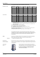
4 selectable standard signals for setpoint and measured value
Features and benefits
•
DIP switch to reduce the k
vs
value to 63 % of the nominal value
•
Potentiometer for adjustment of minimum stroke for suction throttle applications
•
Automatic stroke calibration
•
Forced control input for “Valve closed” or “Valve fully open”
•
LED for indicating the operating state
The refrigerant valve can be driven by Siemens or third-party controllers that deliver a
DC 0/2...10 V or DC 0/4...20 mA output signal.
For optimum control performance, we recommend a 4-wire connection between
controller and valve. When operating on DC voltage, a 4-wire connection is mandatory!
The valve stroke is proportional to the control signal.
4716Z15
2
on
1234
G0 G Y UMZC
1
3
45
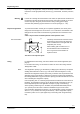
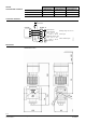
1 Connection terminals
2 LED for indication of operating state
3 Minimal stroke setting
potentiometer Rv
4 Autocalibration
5 DIP switches for mode control
Operator controls
and indicators in the
electronics housing
3 operating modes are possible with the forced control input (ZC):
Override control
•
No function: ZC contact not wired; the valve stroke is determined by control signal Y
•
Forced control – valve fully open: ZC connected directly to G (AC 24 V or DC 24)
•
Forced control – valve closed: ZC connected directly to M or G0 respectively
Also refer to «Connection terminals» on page 8.
Signal priority
Of the possible input signals, override control signal ZC has the highest priority. If ZC is
open, the valve stroke is determined by input Y and the potentiometer setting.
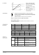
80 %
100 %
4716D01en
0 %
0 %
Hmin
100 %
Hmax
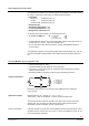
Y-input
Stroke
In the case of the suction throttle valve, it is
essential that a minimum stroke limit be
maintained to ensure compressor cooling
and efficient oil return. This can be
achieved with a reinjection valve, a bypass
line across the valve, or a guaranteed
minimum opening of the valve. The
minimum stroke can be defined via the
controller and control signal Y, or it can be
set directly with potentiometer Rv.
Minimum stroke setting
The factory setting is zero (mechanical stop in counterclockwise direction, CCW). The
minimum stroke can be set by turning the potentiometer clockwise to a maximum of
80 % k
vs
.
Under no circumstances must potentiometer Rv be used to limit the stroke on
expansion applications. It must be possible to close the valve fully.
3/16
Building Technologies Refrigerant Valves PN 40 CE2N4716en
HVAC Products 08.06.2005