
User Manual


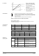

Step 1: For t
c
= 35, calculate the value for t
o
= –10 between values 20 and 40 in the
table; result: 574
Step 2: For t
c
= 35, calculate the value for t
o
= 0 between values 20 and 40 in the
table; result: 553
Step 3: For t
o
= –5, calculate the value for t
c
= 35 between correction factors 574
and 553; calculated in steps 1 and 2; result: 450
Step 4: Calculate the theoretical k
vs
value; result: 0.46 m
3
/h
Step 5: Select the valve; the valve closest to the theoretical k
vs
value is the
MVF661.25-0.4N
Step 6: Check that the theoretical k
vs
value is not less than 50 % of the nominal
k
vs
value
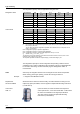
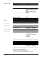
KE-R407C t
0
= –10 °C t
0
= 0 °C Interpolation at t
c
= 35 °C
t
c
= 20 °C
481 376 481 + [(605 - 481) x (35- 20) / (40 - 20)] 574
t
c
= 35 °C 574 553
t
c
= 40 °C 605 612 376 + [(612 - 376) x (35 - 20) / (40 - 20)] 553
Interpolation at t
0
= -5 °C
574 +[(553 - 574) x (-5 - 0) / (-10 - 0)] 450
k
vs
theoretical = 205 kW / 450 = 0.46 m
3
/h
Valve MVF661.25-0.4N is suitable, since: 0.46 m
3
/h / 0.4 m
3
/h x 100 % = 115 % (> 50 %)
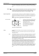
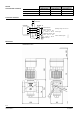
Capacity control
a) Refrigerant valve MVF661…N for capacity control of a dry expansion evaporator.
Suction pressure and temperature are monitored with a mechanical capacity
controller and reinjection valve.
•
Typical control range 0...100 %
•
Energy-efficient operation with low loads
•
Ideal control of temperature and dehumidification
40155A
*
MVL661…N
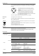
b) Refrigerant valve MVF661…N for capacity control of a chiller.
•
Typical control range 10...100 %
•
Energy-efficient operation with low loads
•
Allows wide adjustment of condensing and evaporating temperatures
•
Ideal for use with plate heat exchangers
•
Very high degree of frost protection
40156A
MVL661…N
A larger valve may be required for low-load operation than is needed for full load
conditions. To ensure that the selected valve will not be too small for low loads, sizing
should take account of both possibilities.
Note
10/16
Building Technologies Refrigerant Valves PN 40 CE2N4716en
HVAC Products 08.06.2005