
Operating Instructions
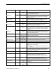
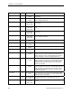
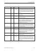
Table Of Contents
- Table of Contents
- How To Use This Manual
- Chapter 1—Hardware
- Chapter 2—Applications for ATEC— Base VAV
- Chapter 3—Applications for ATEC—VAV with Reheat
- Chapter Overview
- Introduction
- Application 2500: VAV Cooling Only
- Application 2501: VAV Cooling or Heating
- Application 2522: VAV with Electric Reheat or Baseboard Radiation
- Application 2523: VAV with Hot Water Reheat (only one reheat valve)
- Application 2524: VAV Series Fan Powered with One Stage of Electric Reheat
- Application 2526: VAV Parallel Fan Powered with One Stage of Electric Reheat
- Application 2473: Slave Mode
- Chapter 4—Point Database
- Chapter 5—Troubleshooting
- Glossary
- Index

Chapter 4—Point Database
4-6 Siemens Building Technologies, Inc.
Descriptor Address
Application Description
CLG D GAIN
65 All except slave
modes
The derivative gain value for the cooling temperature
control loop.
CLG BIAS
66 All except slave
modes
The biasing of the cooling temperature control loop. See
CLG LOOPOUT (Point 79).
HTG P GAIN
67 2501, 2521,
2522, 2523,
2524, 2526
The proportional gain value for the heating temperature
control loop.
HTG l GAIN
68 2501, 2521,
2522, 2523,
2524, 2526
The integral gain value for the heating temperature control
loop.
HTG D GAIN
69 2501, 2521,
2522, 2523,
2524, 2526
The derivative gain value for the heating temperature
control loop.
HTG BIAS
70 2501, 2521,
2522, 2523,
2524, 2526
The biasing of the heating temperature control loop. See
HTG LOOPOUT (Point 80).
FLOW P GAIN
71 All except slave
modes
The proportional gain value for the flow control loop.
FLOW l GAIN
72 All except slave
modes
The integral gain value for the flow control loop.
FLOW D GAIN
73 All except slave
modes
The derivative gain value for the flow control loop.
FLOW BIAS
74 All except slave
modes
The biasing of the flow control loop.
FLOW
75 All except slave
modes
Indicates the actual amount of air currently passing the air
velocity sensor. The value is calculated as a percentage
based on where the value of AIR VOLUME (Point 35) is in
the range between 0 and CTL FLOW MAX (Point 77).
CTL FLOW MIN
76 All except slave
modes
The active minimum flow used as a limit for the flow control
loop. This value is the same as CLG FLOW MIN (Point 31)
if the controller is in cooling mode, or is the same as HTG
FLOW MIN (Point 33) if the controller is in heating mode,
unless it is overridden.
CTL FLOW MAX
77 All except slave
modes
The active maximum flow used as a limit for the flow control
loop. This value is the same as CLG FLOW MAX (Point 32)
if the controller is in cooling mode, or is the same as HTG
FLOW MAX (Point 34) if the controller is in heating mode,
unless it is overridden.
CTL TEMP
78 All except slave
modes
The temperature used as input for the temperature control
loops. This value is the same as the value in ROOM TEMP
(Point 4) unless it is overridden.
CLG LOOPOUT
79 All except slave
modes
The cooling temperature control loop output value in
percent.
HTG LOOPOUT
80 2501, 2521,
2522, 2523,
2524, 2526
The heating temperature control loop output value in
percent.