
Installation Instructions

Document Number 540-1033
Installation Instructions
October 26, 2016
Siemens Industry, Inc. Page 5 of 6
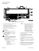
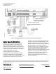
Figure 5. Power Trunk Wiring.
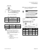
Table 1. Application Descriptions.
Application
Description
Figure
2216
VAV Room Pressurization
with Hot Water Reheat
7
2218
CAV Room Pressurization
with Hot Water Reheat
7
Table 2. Air Velocity Sensor connections.
Application
Supply AVS
HI and LO
Exhaust AVS
HI and LO
2216
Supply Pickup
Exhaust Pickup
2218
Supply Pickup
Exhaust Pickup
CAUTION:
The Room Pressurization Controller –
Electronic Output controls 24 Vac loads
only. The maximum rating is 12 VA for
each DO. Use an interposing 220V 4-relay
module (P/N 540-147) for any of the
following:
VA requirements higher than
maximum
110 or 220 Vac
DC power
Separate transformers used to
power the load.
NOTE: Refer to the unit wiring diagrams or consult
with the local representative if terminations
are missing or are different.
NOTE:
When wiring any actuator that uses a 0
to 10V control signal and ties AC neutral
to DC common, an additional wire
must
connect the actuator AC neutral to the
DC common of the PTEC/TEC AO
being used to control the actuator.
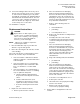
Figure 6. 24 Vac Modulating Control.
Actuator
Symbol
TEC
Connection
Function
Terminal
Connection
Standar
d Color
1
H
Supply (SP)
G
Red
2
C
Neutral (SN)
G0
Black
8
AO3 – 15
(+)
0 to 10V
input signal
Y
Gray
--
C to AO3
16 (-)
Common
jumper
--
--