
User Guide


Chapter 12 - FINlite Graphics Tool
Using the FINlite Graphics Tool
241
Siemens Industry, Inc.
BACnet Field Panel Web Server User Guide
125-3584
2017-07-31
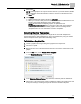
2. Select Drive A.
NOTE: Default graphics can only be saved to Drive A. If you select Drive B, FINlite
will automatically change the selection to Drive A, graying out the Drive B row in
the Drive table.
3. Click Publish.
FINlite automatically renames the file to default.fnl.
When you connect to that panel from the BACnet Field Panel Web Server user
interface, the graphic will display as the default graphic.
NOTE: Because Device Template graphics are published to the
Graphics\Application\AppID folder on the panel, rather than in the Graphics
folder, they cannot be used as default graphics. See the
Creating Device
Template
section for more information on Device Templates.
Creating Device Templates
You can create a graphics template from a single file for reuse with multiple FLN
devices that have the same application ID. This is accomplished by using the
Create
Device Template
feature (also called
relativizing a file
).
To Relativize a Graphics File:
1. Create a graphics file using a background graphic and components.
2. Connect to a panel.
3. Bind points from one of the desired FLN devices to each of the components in the
graphic.
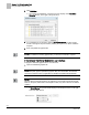
4. From the File menu, select Create Device Template.
The Relativize Mapping window displays.
5. In the Relativize Points to Device drop-down list, select the panel to relativize to.
6. Choose any or all of the device points to relativize by clicking the check boxes next
to the point name(s). Checking the topmost check box will select all points.