
Installation Instructions


Document No. 553-156
Installation Instructions
October 4, 2017
Page 2 of 4
CAUTION:
Seismic Certification Preapproval requires:
∂ Total assembly weight not to exceed 50
lbs. for 20” enclosures assembly or 100
lbs. for 36” enclosure assembly.
∂ Installed Equipment is listed in OSP.
∂ Service box, installed equipment and
wiring management must be installed on
enclosure subpanel.
∂ Center of gravity is offset from origin at
enclosure center to upper left subpanel
surface adding 9 lbs for a 192VA Service
Box or 16 lbs for 384VA Service Box.
Variance due to other installed
components is < 10%.
∂ DIN Rails mounted on rigid subpanel
using three screws supplied each with
pilot hole size 0.136” dia. (29 drill size) for
16 or 14 AWG subpanel. Optional tie bars
use two of same type screw.
∂ Service Box mounted on upper left corner
of rigid subpanel using from material list
(3) ¼”-20 x ½” bolts and flat washers with
¼”-20 lock nuts supplied with Service
Box. Use Close Fit Drill Size F (0.2570).
∂ Certified communication devices may be
fastened to subpanel and power packs to
outlet with 3M
®
Dual Lock
®
Fasteners
SJ3560 (Type 250). Use two pair for
devices and one pair for power packs.
Minimum 1” square per 2 lbs.
General use:
∂ Optional Side Wall Kit installed where
Service Box cannot be installed close
enough to enclosure side to prevent
inadvertent access to line voltage.
Installation
NOTE: Follow all safety regulations and local codes
when installing this equipment.
NOTE: Determine the mounting location of all
installed equipment on enclosure subpanel
prior to drilling DIN rail, tie bar, and Service
Box pilot holes. Ensure room for Kit label.
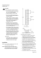
Figure 1, DIN Rail Dimensions (4) in Kit.
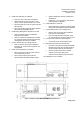
1. Install Service Box on subpanel.
∂ See Figure 2 and Figure 3 for dimensions,
weights, keep outs and sticker location.
∂ Total length includes wire cover which may
overhang subpanel to reach top of enclosure.
∂ Right side may overhang subpanel by
maximum 1/2” to reach right enclosure wall.
∂ Ensure enclosure locking mechanisms do not
interfere with installed Service Box.
∂ Drill three Size F (close fit) holes for bolts.
∂ Insert ¼”-20 bolts from material list in back of
subpanel, through mounting holes and secure
with three supplied SB ¼”-20 lock nuts.
∂ Optional install three ¼”-20 x ½” PEM studs
(not supplied) per manufacturer specification
in the subpanel at locations shown.
∂ Optional Service Box Side Wall, Refer to 553-
135 Installation Instruction.
∂ Place Seismic Sticker on front of Service Box.