
User Manual


Siemens Building Technologies CE1N2822E / 29.11.1998
Landis & Staefa Division 7/8
General data Characteristic flow values
Operating voltage (safety extra
low voltage to EN 60730) AC 24 V
Frequency 50 Hz
Power consumption 3.2 VA
Degree of protection to EN 60529 IP52
Safety class to EN 60730 III
Electromagnetic compatibility
Immunity EN 50082-2
Emissions EN 50081-1
Connecting cablel
Length 1 m
Max. permissible extension 10 m
Max. length of connecting cable
at terminal P1 (pulse source) 10 m
Permissible ambient temperature
Operation 5...50 °C
Transport and storage -25...+65 °C
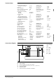
Mounting length 110 mm
Connecting thread 1”
Fittings (ALG82) 1” - ¾”
Weight 2.1 kg
Max. flow temperature 90 °C
Min. flow temperature 20 °C
Max. return temperature 90 °C
Min. return temperature 20 °C
Max. temperature differential 70 K
Min. temperature differential 2 K
Max. static pressure 10 bar (PN10)
Min. static pressure 0 bar
Max. pressure drop across valve 900 mbar
Water quality to VDI 2035
Conductance < 150 µS/cm
Oxygen (O
2
) < 0.2 mg/l
Alkaline earths (Ca + Mg) < 0.02 mg/l
Phosphate (PO
4
) < 2.5 mg/l
Hydrogen sulphide (H
2
S) < 0.1 mg/l
WRV82.200
Nominal flow rate 200 l/h
Max. flow rate 200 l/h
Min. flow rate 25 l/h
Flow rate display range 20...300 l/h
Max. pressure drop at
nominal flow 120 mbar
WRV82.400
Nominal flow rate 400 l/h
Max. flow rate 400 l/h
Min. flow rate 50 l/h
Flow rate display range 40...600 l/h
Max. pressure drop at
nominal flow 120 mbar
WRV82.750
Nominal flow rate 750 l/h
Max. flow rate 750 l/h
Min. flow rate 90 l/h
Flow rate display range 75...1125 l/h
Max. pressure drop at
nominal flow 120 mbar
WRV82.1500
Nominal flow rate 1500 l/h
Max. flow rate 1500 l/h
Min. flow rate 180 l/h
Flow rate display range 150...2250 l/h
Max. pressure drop at
nominal flow 150 mbar
G1
G2 MB DB
G1 G2 MB DB
G1 G2
Y1
G1
G2 MBDB
U1
B1
D1
D2
M
P1
P1
G1
G2 MB
DB
D1
MD
P1
D1 P1
D1
MD P1
MD
X1
N1
DB MB
G2
G1
AC 24 V
2822A01
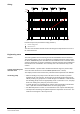
Colour coding of
cable
G1 white
G2 brown
MB blue
DB pink
D1 grey
MD green
P1 yellow
B1 Room unit QAW...
N1 Central unit OZW30 or bus power pack TRW30
P1 Any non-SYNERGYR meter with a pulse source, (e.g. for d.h.w.)
U1 Pulse adapter AEW2.1
X1 Conduit box ALW30
Y1 Control and heating cost allocation valve WRV82...
Technical data
Connection diagram