
User Manual


CE1N2822E / 29.11.1998 Siemens Building Technologies
6/8 Landis & Staefa Division
The WRV82... must be mounted in the return pipe.
When laying the pipes, the adapter piece must be fitted. The required fittings for the
adapter piece are to be mounted on site.
Prior to mounting the WRV82..., the plant must be thoroughly flushed.
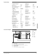
Above the control and heating cost allocation valve, there must be a clearance of at
least 50 mm to make certain the display can be read. To the right of the valve, the
clearance required is 100 mm, allowing the address plug to be fitted and the service unit
to be connected (refer to "Dimensions").
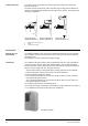
The control and heating cost allocation valve may be mounted horizontally or vertically,
but not upside down:
Permitted Yes Yes Yes (note: No
LCD upside down!
The valve body may not be lagged.
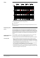
When connecting the 7-wire cable of the valve to the conduit box, the individual wires
can be identified by their colours (refer to “Connection diagram“).
Commissioning includes:
–
Connection of the WRV82... to the conduit box
–
Fitting the address plugs
–
Setting the parameters of the whole SYNERGYR plant
–
Sealing of units
The valve's parameters will be set by Landis & Staefa staff after mounting, thus ensur-
ing a uniform metering start.
If the reference room is equipped with thermostatic radiator valves, they must be locked
in their fully open position.
Mounting notes
Mounting location
Prior to mounting
Mounting
2821Z19
Electrical installation
Commissioning
notes