
User Manual


Siemens Building Technologies CE1N2822E / 29.11.1998
Landis & Staefa Division 5/8
p
1000
100
10
1
0,07 0,1 0,5 1 1,5 2
V
2822D02
∆
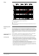
Pressure drop curves (measurement range position 2)
∆
p Pressure drop in mbar
Flow rate in m
3
/h
The valve size should be selected such that the design flow represents 50 to 100 % of
the nominal flow rate.
The local regulations for heat metering and electrical installations must be observed.
The operating voltage of AC 24 V is supplied by an isolating transformer which powers
the whole SYNERGYR system and which must be installed near the central unit. When
sizing the transformer, the power consumption of all units connected to the building bus
must be taken into consideration. The secondary side of the transformer may not be
earthed.
Since the WRV82... operates with a variable measurement range, the pressure drop
across the valve should never exceed
0.12
bar
(WRV82.1500: 0.15 bar).
The surplus pressure must be reduced by a throttle mounted upstream of the WRV82...
•
When the heating zone pump runs and all valves are shut, and with no pressure
regulation at the end of the pipe, the flow pipe has to absorb the full pump pressure
without producing any pump head. To avoid damage to the WRV82... in this situation,
the circulating pumps need to be appropriately sized: at a flow rate of 0 m
3
, the pump
head of the heating zone pump may not exceed 0.8 bar
•
To avoid damage to the circulating pump and the control and heating cost allocation
valve, a spill valve should be installed at the end of the piping system
•
For differential pressure control, it is recommended to use a speed-controlled pump
•
The temperature measuring unit QAB30 acquires the temperature of each zone. The
maximum zone length on a riser may be 30 m
Sizing
Engineering notes
General
Control and heating cost
allocation valve
Circulating pump